Fig. 5.1. Different forms of guide bunds (Para 5.2.2.1)10
![Fig. 5.2. Extent of protection provided by parallel and divergent guide bunds [Para 5.2.2.1 (i)]](irc.gov.in.089.1997_files/irc.gov.in.089.1997-2.png)
Fig. 5.2. Extent of protection provided by parallel and divergent guide bunds
[Para 5.2.2.1 (i)]
This library of books, audio, video, and other materials from and about India is curated and maintained by Public Resource. The purpose of this library is to assist the students and the lifelong learners of India in their pursuit of an education so that they may better their status and their opportunities and to secure for themselves and for others justice, social, economic and political.
This item has been posted for non-commercial purposes and facilitates fair dealing usage of academic and research materials for private use including research, for criticism and review of the work or of other works and reproduction by teachers and students in the course of instruction. Many of these materials are either unavailable or inaccessible in libraries in India, especially in some of the poorer states and this collection seeks to fill a major gap that exists in access to knowledge.
For other collections we curate and more information, please visit the Bharat Ek Khoj page. Jai Gyan!
(First Revision)
Published by:
INDIAN ROADS CONGRESS
Jamnagar House, Shahjahan Road,
New Delhi-110011
1977
Price Rs.120/-
(plus packing & postage)
BRIDGES SPECIFICATIONS AND STANDARDS COMMITTEE
(as on 18-4-95)
| Sl. No. | Name | Address |
| 1 | M.V. Sastry* (Convenor) |
DG (RD), Ministry of Surface Transport (Roads Wing), New Delhi-110 001 |
| 2. | M.R. Kachhwaha (Member-Secretary) |
Chief Engineer (B) S&R, Ministry of Surface Transport (Roads Wing), New Delhi |
| 3. | S.S. Chakraborty |
Managing Director Consulting Engg. Service (I) Pvt. Ltd., 57, Nehru Place, New Delhi-110 019 |
| 4. | A.D. Narain | Chief Engineer (Bridges), MOST (Roads Wing), New Delhi-110001 |
| 5. | Prof. D.N. Trikha | Director, Structural Engg. Res. Centre, Sector-19, Central Govt. Enclave, Kamla Nehru Nagar, PB No. 10, Ghaziabad-201 002 |
| 6. | R.H. Sarma |
Chief Engineer, MOST (Retd.), C-7/175, Safdarjung Dev. Area, New Delhi-110 016 |
| 7. | Ninan Koshi | DG(RD) & Addl. Secy, MOST (Retd), 56, Nalanda Apartment, Vikaspuri, New Delhi |
| 8. | S.N. Mane |
Sr. Vice President Lok Global & National Constn. Ltd., Lok Centre, Marol-Maroshi Road, Andheri (E), Mumbai-400 059 |
| 9. | G. Bhatwa |
Chief Engineer (NH) P.W.D., B&R Branch, Patiala |
| 10. | A.G. Borkar | A-l, Susnehi Plot No. 22, Arun Kumar Vaidya Nagar, Bandra Reclamation, Mumbai-400 050 |
| 11. | N.K. Sinha |
Chief Engineer (PIC) Ministry of Surface Transport (Roads Wing), Transport Bhavan, New Delhi-110 001 |
| 12. | P.B. Vijay |
Addl. Director General (Border), Central Public Works Deptt., Nirman Bhavan, Room No. 424, New Delhi-110011. |
| 13. | H.P. Jamdar |
Secretary to the Govt. of Gujarat, R&B Deptt., Block No. 14, Sachivalaya Complex, Gandhinagar-382 010 |
| 14. | G.C. Mitra |
Engineer-in-Chief (Retd.) A-l/59, Saheed Nagar, Bhubaneswar-751 007 |
| 15. | Surjeet Singh | Secretary to the Govt. of Madhya Pradesh, E-2/CPC, Char Imli, Bhopal-462 016 |
| 16. | V. Murahari Reddy |
Engineer-in-Chief (R&B), Errum Manzil, Hyderabad-580 482 |
| 17. | M.V.B. Rao |
Head, Bridge Division, Central Road Research Institute, P.O. CRRI, Delhi-Mathura Road, New Delhi-110 020 |
| 18. | Prof. C.S. Surana |
Civil Engg. Department, Indian Institute of Technology, Hauz Khas, New Delhi-110 016 |
| 19. | C.R. Alimchandani | Chairman & Managing Director, STUP Consultants Ltd., 1004-5 & 7, Raheja Chambers, 213, Nariman Point, Mumbai-400 021 |
| 20. | N.C. Saxena |
Director Intercontinental Consultants & Technocrats (P) Ltd., A-ll, Green Park, New Delhi-110 016 |
| 21. | M.K. Bhagwagar |
Consulting Engineer, Engg. Consultants (P) Ltd., F-14/15, Connaught Place, New Delhi-110 001 |
| 22. | B.S. Dhiman |
Managing Director, Span Consultants (P) Ltd., Flats 3-5, (2nd Floor), Local Shopping Centre, J-Block, Saket, New Delhi-110 017 |
| 23. | S.R. Tambe |
Secretary (R), P.W.D., Mantralaya, Mumbai-400 032 |
| 24. | S.A. Reddi |
Dy. Managing Director, Gammon India Ltd., Gammon House, Veer Savarkar Marg, Prabhadevi, Mumbai-400 025 |
| 25. | Dr G.P. Saha |
Chief Engineer, Hindustan Construction Co. Ltd, Hincon House, Lal Bahadur Shastri Marg, Vikhroli (West), Mumbai-400 083 |
| 26. | P.Y. Manjure |
Principal Executive Director, The Freyssinet Prestressad Concrete Co. Ltd., 6/B, 6th Floor, Sterling Centre, Dr. Annie Besant Road., Worli, Mumbai |
| 27. | Papa Reddy |
Managing Director Mysore Structurals Ltd., 12, Palace Road, Bangalore-560 052 |
| 28. | Vijay Kumar | General Manager UP State Bridge Constn. Co. Ltd., 486, Hawa Singh Block, Khel Gaon, New Delhi-110049 |
| 29. | P.C. Bhasin | 324, Mandakini Enclave, Greater Kailash-II, New Delhi-110 019 |
| 30. | D.T. Grover | D-1031, New Friends Colony, New Delhi-110 065 |
| 31. | Dr V.K. Raina | B-13, Sector-14, NOIDA (UP) |
| 32. | N.V. Merani | A-47/1344, Adarsh Nagar, Worli, Mumbai -400 025 |
| 33. | C.V. Kand |
Consultant E-2/136, Mahavir Nagar, Bhopal-462 016 |
| 34. | M.K. Mukherjee | 40/182, Chitranjan Park, New Delhi-110 019 |
| 35. | Mahesh Tandon |
Managing Director Tandon Consultant (P) Ltd., 17, Link Road, Jangpura Extn., New Delhi-110 014 |
| 36. | U. Borthakur |
Secretary, PWD B&R (Retd.) C/o Secretary, PWD B&R, Shillong-793 001 |
| 37. | Dr. T.N. Subba Rao | Construma Consultancy (P) Ltd., 2nd Floor, Pinky Plaza, 5th Road, Khar (W), Mumbai-52 |
| 38. | S.C. Sharma |
Chief Engineer (R) S&R, Ministry of Surface Transport (Roads Wing), New Delhi-110 001 |
| 39. | The Director | Highways Research Station, Guindy, Madras-25 |
| 40. | G.P. Garg |
Executive Director (B&S), Research Designs & Standards Organisation, Lucknow-226 011 |
| 41. | Vinod Kumar |
Director & Head (Civil Engg.), Bureau of Indian Standards, Manak Bhavan, New Delhi-110 002 |
| 42. |
President, Indian Roads Congress |
K.K. Madan -Ex-Officio Director General (Works), CPWD, New Delhi-110 011 |
| 43. | DG(RD) & Hon. Treasurer, Indian Roads Congress |
M.V. Sastry - Ex-Officio |
| 44. |
Secretary, Indian Roads Congress | S.C. Sharma - Ex-Officio |
| Corresponding Members | ||
| 1. | Shitala Sharan |
Adviser Consultant, Consulting Engg. Services(Ι) Pvt. Ltd., 57, Nehru Place, New Delhi-110019 |
| 2. | Dr. M.G. Tamhankar |
Dy. Director & Head, Bridge Engg. Division, Structural Engg. Research Centre, Ghaziabad (U.P.) |
| * ADG(B) being not in position. The meeting was presided by Shri M.V. Sastry, DG(RD) Govt of India MOST | ||
“The Guidelines for Design and Construction of River Training and Control Works for Road Bridges” were first published in 1985. These guidelines did not include floor protection works and maintenance of the protective works. Also need for verifying the recommendations of physical model studies on mathematical model has been felt. Further, new materials like geo-synthetics now find use in the strengthening of earthen embankment, slope protection and launching apron. As such need for revising the existing guidelines was felt. Accordingly, a Committee comprising of the under mentioned members was formed to review the existing guidelines:
| L.S. Bassi | ... | Convenor |
| M.P. Marwah | ... | Member-Secretary |
| MEMBERS | ||
| S.P. Chakrabarti | Rep. of Central Water Power Res. Station | |
| K.P. Poddar | (S.B. Kulkarni) | |
| N.K. Sinha | Rep. of RDSO (V.K. Govil) | |
| H.S. Kalsi | B.K. Bassi | |
| G. Bhatwa | Rep. of Central Water Commission | |
| H.N. Chakraborty | (G. Seturaman) | |
| S. Manchaiah | Research Officer, Hydraulic Div. Irrigation | |
| M. ChandersekheranCE (Design) Bldg. and | and Power Institute Rep. of DGBR (S.P. Mukherjee) | |
| Administration, | Rep. of IRI (Harish Chandra) | |
| Andhra Pradesh, PWD Director, H.R.S., Madras |
||
| EX-OFFICIO MEMBERS | ||
| President, IRC (M.K. Agarwal) | Hon. Treasurer, IRC (Ninan Koshi) | |
| Secretary, IRC (D.P. Gupta) | ||
| CORRESPONDING MEMBERS | ||
| J.S. Marya | B.J. Dave | |
| J.S. Sodhi | Coastal Engineer, B.P.T. | |
The Protective Works Committee (B-9) reviewed the existing guidelines and finalised the modifications in their meeting held on 13-8-93. These guidelines have since been approved by the Bridges Specifications & Standards Committee in their meeting held on 18.4.95. These were approved by the Executive Committee and the Council of the Indian Roads Congress in their meetings held on 19-4-95 and 1-5-95 respectively.
The guidelines cover the layout and design of river training works and approach embankment protection works for ensuring safety of the bridges and their approaches. These guidelines also deal with some of the construction and maintenance aspects. Protection works for open and shallow foundations are also covered.
The scope of these guidelines is limited only to some salient aspects of design and construction of the protection works mentioned above and does not extend to the much wider associated problems of river behaviour, control and bridge hydraulics, etc.
The necessity or otherwise of the guidebunds, spurs and other protective works has to be decided upon carefully after observing the behaviour of the river at the site under consideration. Data about the protection works at other sites on upstream or downstream of the site under consideration can also be a good guide.
River training works are costly and their maintenance cost is also very high. In case, their location, configuration and size is not decided properly, these works can cause damaging effects also. Therefore, they have to be provided judiciously.
For bridges across major rivers, the extent and configuration of the protective works should be decided with the help of physical models. For accuracy, the results obtained from physical models may be further checked on mathematical models by the same research station which carried out physical model studies.
Given inadequate knowledge of and uncertainties around many2
aspects of bridge hydraulics and river behaviour characteristics in general, these guidelines cannot obviously claim to have any general validity of application. These are to be deemed as a guide to good practice of design and construction of the protection works compatible with the current experience and knowledge in the subject area. For particular applications, these guidelines may have to be modified and supplemented in each case based on subjective and objective judgement of the engineer, to cater for site, river and specific requirements of a bridge structure.
The following definitions shall apply for the purpose of these guidelines.
guide the river flow past a bridge without causing damage to it and its approaches. These are generally constructed in the direction of flow on one or both flanks, depending on the site conditions.
The following information in line with the provisions of IRC:5-1985, and amplified hereinafter shall be furnished. The nature and extent of the data to be collected in each case will, however, depend upon the importance of the bridge.
confluence of two rivers, the reach to be considered in respect of both of these should be at least 1.5 km upstream of the extent of back water influence in the tributaries under highest flood level.
The site plan should extend for a distance of atleast 3 km upstream and 1 km downstream and should indicate river course during high floods and dry season duly superimposed in different colours for as many years as available. The contours or spot levels should extend over this area at a contour interval varying from 0.5 m in flat terrain to 2 m for steep terrain.
The nodal points which are not affected by meandering action of the river should be suitably marked on the plan.
4.2. Hydrological Data
Existing environmental/ecological conditions in the immediate vicinity of the structure and the effect of the proposed river training/control works on the same.
soil, stone quarry having 40 kg (or 300 mm size) boulders and other materials suited for river training and control works.
The design discharge for which the river training works are to be designed shall be in accordance with the recommendations of IRC: 5-1985 “Standard Specifications and Code of Practice for Road Bridges, Section I, General Features of Design (Sixth Revision)”.
The mean depth of scour (dsm) below the highest flood level, shall be calculated in accordance with provisions of IRC:5.
Afflux shall be calculated as per formula given in Appendix 1 (a).
For bridges across rivers carrying discharges more than 3000 m3/sec., afflux shall be calculated as per the method given in Appendix 1 (b) also and a reasonable value adopted.
The provisions given hereunder apply only to guide bunds for bridges across alluvial rivers. Guide bunds for bridges across sub-montane rivers need special consideration which are discussed in para 9.8
The alignment shall be such that the pattern of flow remains as uniform through all the spans of the bridge as may be possible with minimum return currents.
The alignment of approach embankment should be so chosen that it is not affected by the worst possible embayment which is influenced by the length of guide bunds. In general these are aligned in line with the axis of bridge upto high defined banks. In case the alignment of road has to be given a curve before reaching the high defined banks, it has to be provided towards the downstream side and not towards upstream side.
Guide bunds can be classified:
The guide bunds can be divergent, convergent and parallel, Fig. 5.1.
Fig. 5.1. Different forms of guide bunds (Para 5.2.2.1)10
Fig. 5.2. Extent of protection provided by parallel and divergent guide bunds
[Para 5.2.2.1 (i)]
Guide bunds can be straight or elliptical with a circular or multi radii curved head, Fig. 5.3. In case of acute curved channel approaches, it has been found that the flow after striking the mole head does not follow the profile of parallel guide bunds with circular heads but separates from the boundary as illustrated in, Fig. 5.4. It results in an oblique approach of flow to the bridge thereby making some of the end spans completely ineffective while increasing the intensity of flow in the remaining bays. To improve the flow conditions the provision of elliptical guide bunds is suggested. The ratio of major to minor axis is generally kept in the range of 2 to 3.5. Elliptical guide bunds have generally been found more suitable in case of wide flood plain/ rivers as compared to straight guide bunds.11
Fig. 5.3. Geometrical shape of guide bunds
(Para 5.2.2.2)12
Fig. 5.4. (a) Straight guide bund with circular head
(b) Elliptical guide bund followed by circular ARC (Para 5.2.2.2.)13
Any other type of guide bunds differing in form or shape may be provided,' warranted by site conditions and supported by the model studies.
For wide alluvial belt, the length of guide bund should be decided from two important considerations, namely the maximum obliquity of the current and the permissible limit to which the main channel of the river can be allowed to flow near the approach embankment in the event of river developing excessive embayment behind the guide bunds.
The radius of the sharpest loop should be ascertained from the data of the acute loops formed by the river during the past. If survey plans do not reveal the presence of a sharpest loop, it may be calculated as follows:
Of available loops (Fig. 5.5.) calculate radius (r) of each at centre line by formula.
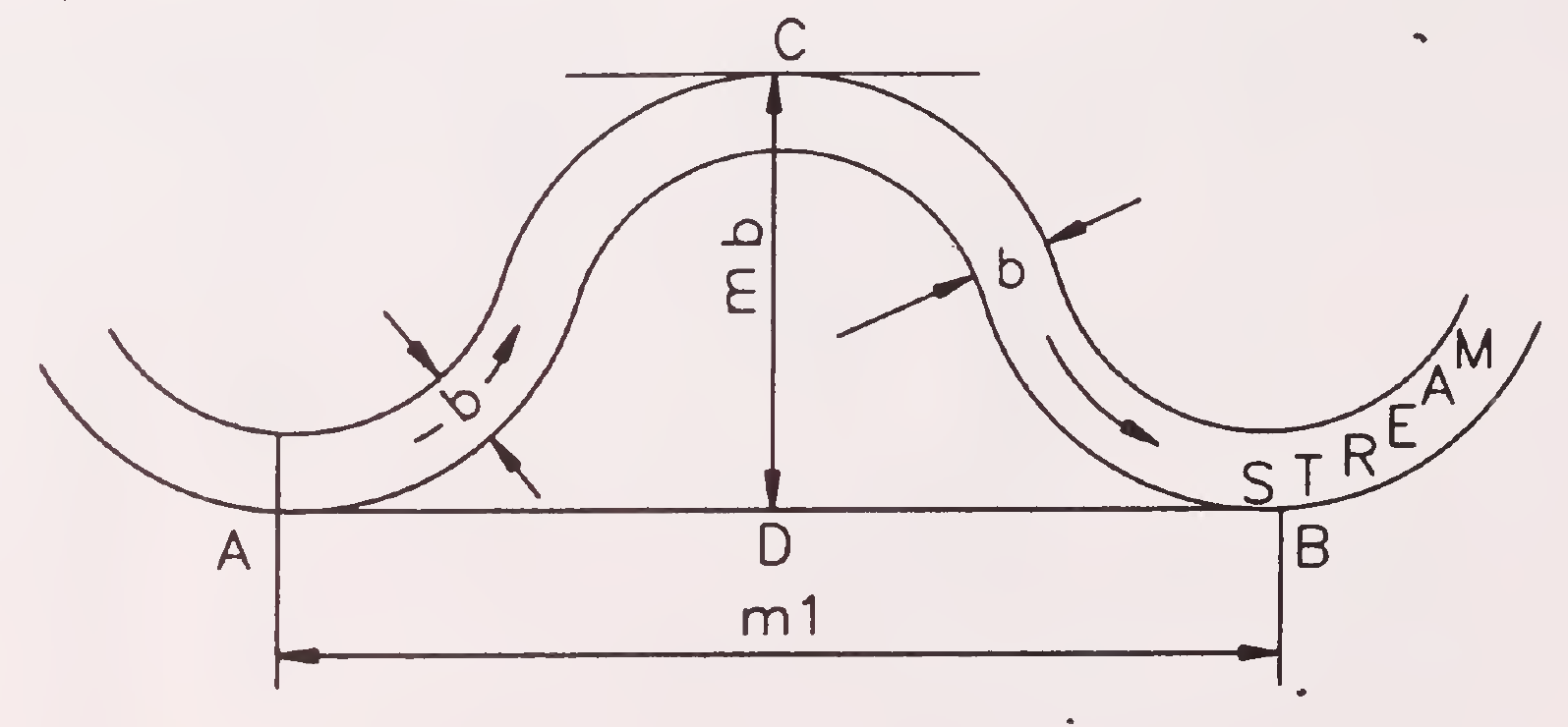
Fig. 5.5. Sketch showing a loop in a river (Para 5.2.3.2.)
Notations:
| mi | = Meander Length |
| mb | = Meander Belt |
| b | = Average width of channel during floods14 |
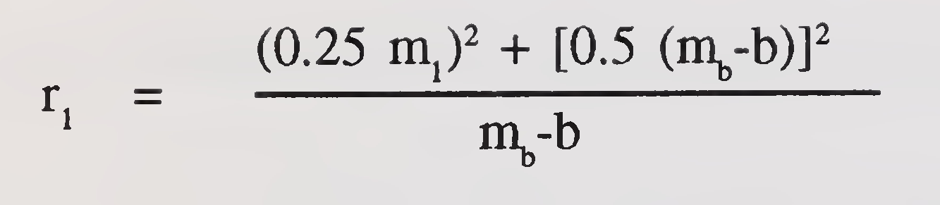
| where | r1 | = radius of loop in metre |
| m1 | = meander length in metre | |
| mb | = meander belt in metre | |
| b | = average width of channel during floods in metre |
From the above, calculate the average radius of the loop. This average radius divided by 2.5 for rivers having maximum discharge upto 5000 m3/ sec. and by 2.0 for maximum discharge above 5000 m3/sec. gives radius of the sharpest loop. After having determined the radius of the sharpest loop, the single or double loop are laid out on survey plan that contains the alignment of approach embankments and high banks and it may be ensured that the safe distance between the anticipated sharpest loop and approach embankment is not less than L/3 where L is the length of the bridge. However, specially in the case of meandering rivers, this safe distance may be suitably increased.
The length of guide bund on the upstream side is normally kept as 1.0 L to 1.5 L where no model studies are carried out. For elliptical guide bund the upstream length (semi major axis al) is generally kept as 1.0 L or 1.25 L.
Guide bunds will generally not be able to protect the approach bank within the Khadir for more than three times its lengths, as evolved above, beyond the abutments on the upstream side. Where approach banks are more than three times the length of guide bunds, additional training/ protective measures may be necessary to protect the approach banks.
On downstream side of the structure, the river tries to fan out to regain its natural width. Here the function of guide bund is to ensure that the river does not attack approach embankments. Length equal to 0.2 L is generally found to be adequate. In special situations, the length may have to be suitably increased or decreased depending upon the circumstances.15
Function of curved head is to guide river flow smoothly and axially through the bridge keeping the end spans active. A too small radius gives a kick to the river current making it oblique and so larger radius to attract and guide the river flow is needed. However, as it is uneconomical to provide a very large radius, it may be kept as small as possible consistent with proper functioning of guide bund.
Radius of upstream mole head may be kept 0.4 to 0.5 times the length of the bridge between abutments, but it should not be less than 150 m nor more than 600 m unless indicated otherwise by model studies.
Radius of curved tail may be from 0.3 to 0.5 times the radius of upstream mole head.
The angle of sweep of the upstream mole head is kept 120° to 140° and that for the curved tail is kept 30° to 60°.
In case of elliptical guide bunds, the elliptical curve is provided upto the quadrant of an ellipse and is followed by multi-radii or single radius circular curve, Fig. 5.3. The shape should be finalised preferably on the basis of model studies.
For guide bunds of bridges across major rivers, hydraulic model studies are recommended for deciding the various design features.
The top width of guide bunds for bridges across major rivers is generally kept at least 6 metre to permit passage of vehicles for carriage of materials.
The free board should be measured from the pond level behind the guide bund after taking into consideration the afflux, kinetic energy head and water slope.16
The minimum free board to top of guide bund above the pond level is generally kept as 1.5 m to 1.8 m. This may be suitably increased in the case of guide bunds for bridges across major rivers. The top of guide bund should follow the slope of river flow.
In case where model studies are conducted for guide bunds, the model studies will also indicate the highest anticipated pond level immediately behind the guide bunds and at suitable intervals along the approaches, wherever, significant ponding up is anticipated.
In cases where rivers have aggrading tendencies i.e. deposition of silt/sand in bed over the years, suitable extra provision will have to be made while working out the pond level to allow for the effect of aggradation.
The side slope of the guide bunds may be determined from the consideration of slope stability of embankment and from hydraulic gradient considerations. Generally a side slope of 2 (H): 1 (V) is adopted for predominently cohesionless materials.
The river side earthern slope of guide bunds are protected against river action by covering them with stones/concrete slabs. The pitching is intended to remain in its laid position. It should be extended upto the top of guide bund and tucked inside for a width of at least 0.6 m.
Rear slopes of guide bunds are not subjected to direct attack of the river and may be protected against ordinary wave splashing by 0.3 - 0.6 m thick cover of clayey or silty earth and turfed. Where moderate to heavy wave action is expected slope pitching should be laid upto a height of 1 m above the pond level.
For the design of pitching on the river side, the factors to be taken into consideration are size/weight of the individual stone, its shape and gradation, thickness and slope of pitching and type of filter underneath. The predominant flow characteristic which effects the stability of the pitching is velocity along the guide bund. Other factors like obliquity of flow, eddy action, waves, etc. are17
indeterminate and may be accounted for by providing adequate margin of safety over the size obtained from velocity considerations.
The size of stone required on the sloping face of guide bunds to withstand erosive action of flow may be worked out from the following equation:
d = Kv2
where
K = 0.0282 for face slope of 2:1 and 0.0216 for face slope of 3:1
d = equivalent diameter of stone in metre
v = mean design velocity in metre/sec.
The weight of stone can be determined by assuming spherical stone having a specific gravity of 2.65 (average). Plot of size and weight of stone against velocity of flow for different face slopes are given in Fig 5.6. For velocities upto 5 m/sec., the size and weight of stone is also given in Table 5.1.
| Mean design velocity m/sec. | Minimum size and weight of stone | ||||
| Slope 2:1 | Slope 3:1 | ||||
| Diameter (cm) | Weight (kg) | Diameter (cm) | Weight (kg) | ||
| Upto | 2.5 | 30 | 40 | 30 | 40 |
| 3.0 | 30 | 40 | 30 | 40 | |
| 3.5 | 35 | 59 | 30 | 40 | |
| 4.0 | 45 | 126 | 35 | 59 | |
| 4.5 | 57 | 257 | 44 | 118 | |
| 5.0 | 71 | 497 | 54 | 218 | |
|
Notes:
|
|||||
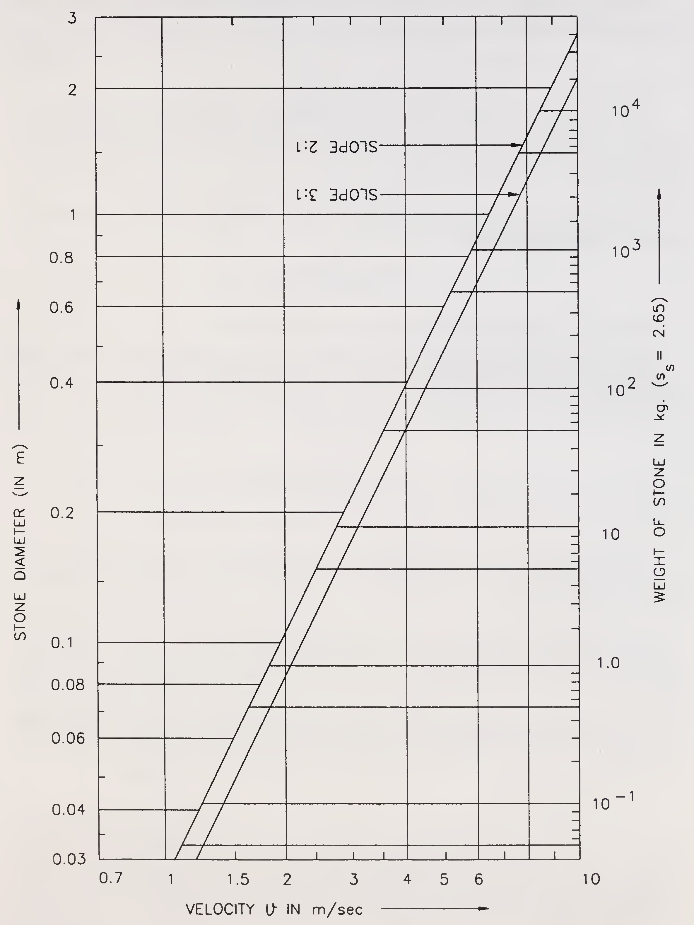
Fig. 5.6. Size of stone pitching v/s velocity (Para 5.3.5.1)19
The thickness of pitching (t) may be determined from the following formula:
t = 0.06 Q1/3
where Q = design discharge in m3/sec.
The thickness of stone pitching computed from the above formula shall be subject to an upper limit of 1.0 m and a lower limit of 0.3 m. The thickness of pitching may be suitably increased in case of guide bunds of bridges across major rivers.
For the stones in wire crate the thickness of pitching (t) may be determined from the following formula:
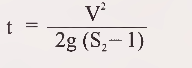
Where S2 = Specific gravity of stone normally taken as 2.65
However, while working out size of wire crate as per Appendix-2 the mass specific gravity (Sm) and porosity (c) can be worked out using following relationship
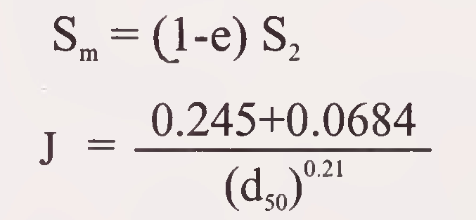
Where d50 = Mean diameter of stones used in crate in millimeters
Quarry stone is preferable to round boulders as the latter roll off easily. Angular stones fit into each other better and have good interlocking characteristics.
In hand placed pitching, the stone of flat stratified nature should be placed with the principal bedding plane normal to the slope. The pattern of laying shall be such that the joints are broken and voids are minimum by packing with spalls wherever necessary and the top surface is as smooth as possible. In the case of guide bunds for bridges across major rivers, stone masonry bands may be provided at suitable intervals if considered necessary.
Filter shall consist of sound gravel, stone, jhama (overbumt) brick ballast and coarse sand. Now a days in other countries geotextiles are also being used as filter material. But, in India these have not been used extensively. As such these may be used only after considering their cost effectiveness and under expert guidance.
Provision of a suitably designed filter is necessary under the slope pitching to prevent the escape of underlying embankment material through the voids of stone pitching/cement concrete slabs as well as to allow free movement of water without creating any uplift head on the pitching when subjected to the attack of flowing20
water and wave action, etc. In order to achieve this requirement, the filter may be provided in one or more layers satisfying the following criteria:
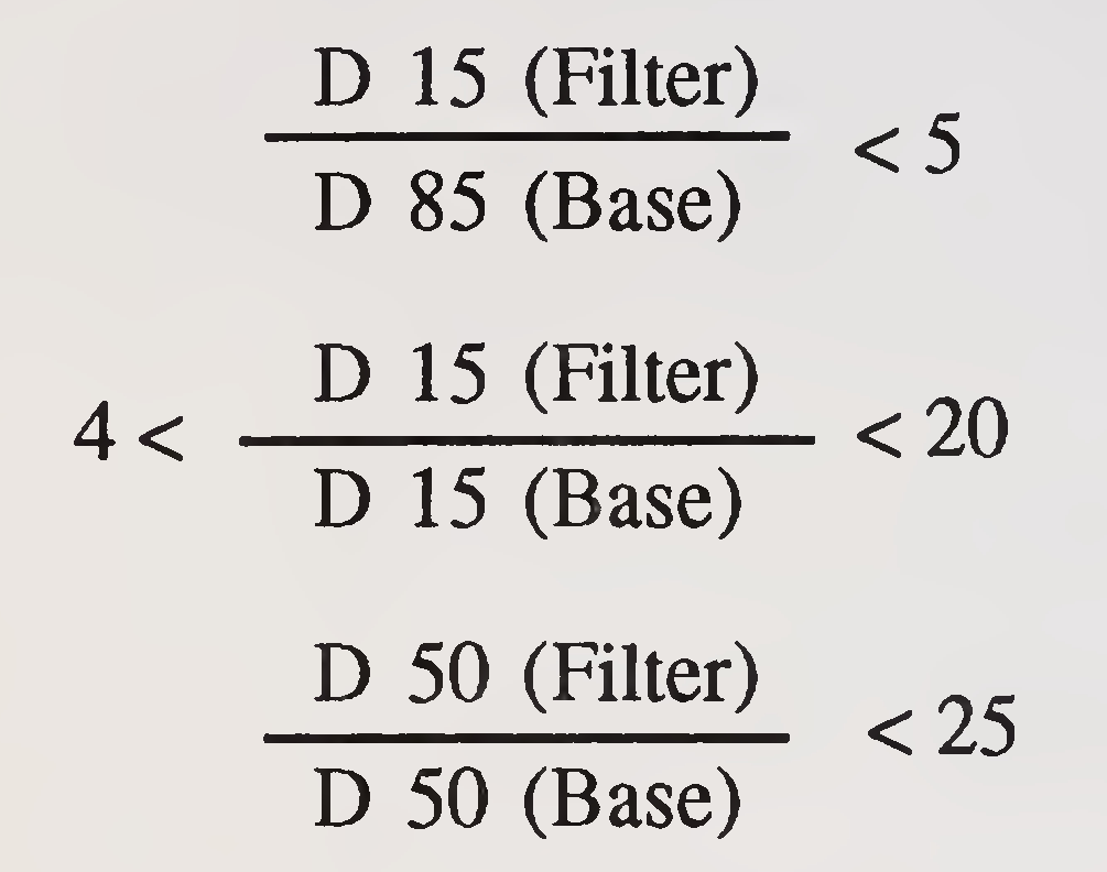
Notes:
Launching apron shall be provided for the protection of toe and it shall form a continuous flexible cover over the slope of the possible scour hole in continuation of pitching upto the point of deepest scour. The stone in the apron shall be designed to launch along the slope of the21
scour hole so as to provide a strong layer that may prevent further scooping out of river bed material. The size and shape of apron depends upon the size of stone, thickness of launched apron, the depth of scour and the slope of launched apron. At the junction of slope pitching with launching apron, a toe wall shall be provided as shown in Fig. 5.7, so that pitching does not rest directly on the apron. It will protect the slope pitching from falling during the launching of apron even when the apron is not laid at low water level.

Fig. 5.7. Sketch showing toe wall at junction of slope pitching and launching apron
(Para 5.3.7.1.)
The size of stone required for launching apron to resist mean design velocity (average velocity) is given by the formula:

where
ϑ = mean design velocity in metre/sec
d = equivalent diameter of stone in metre
The weight of stone can be determined by assuming spherical stones having a specific gravity of 2.65 (average). Plot of size and weight of stone against velocity is given in Fig. 5.8.22
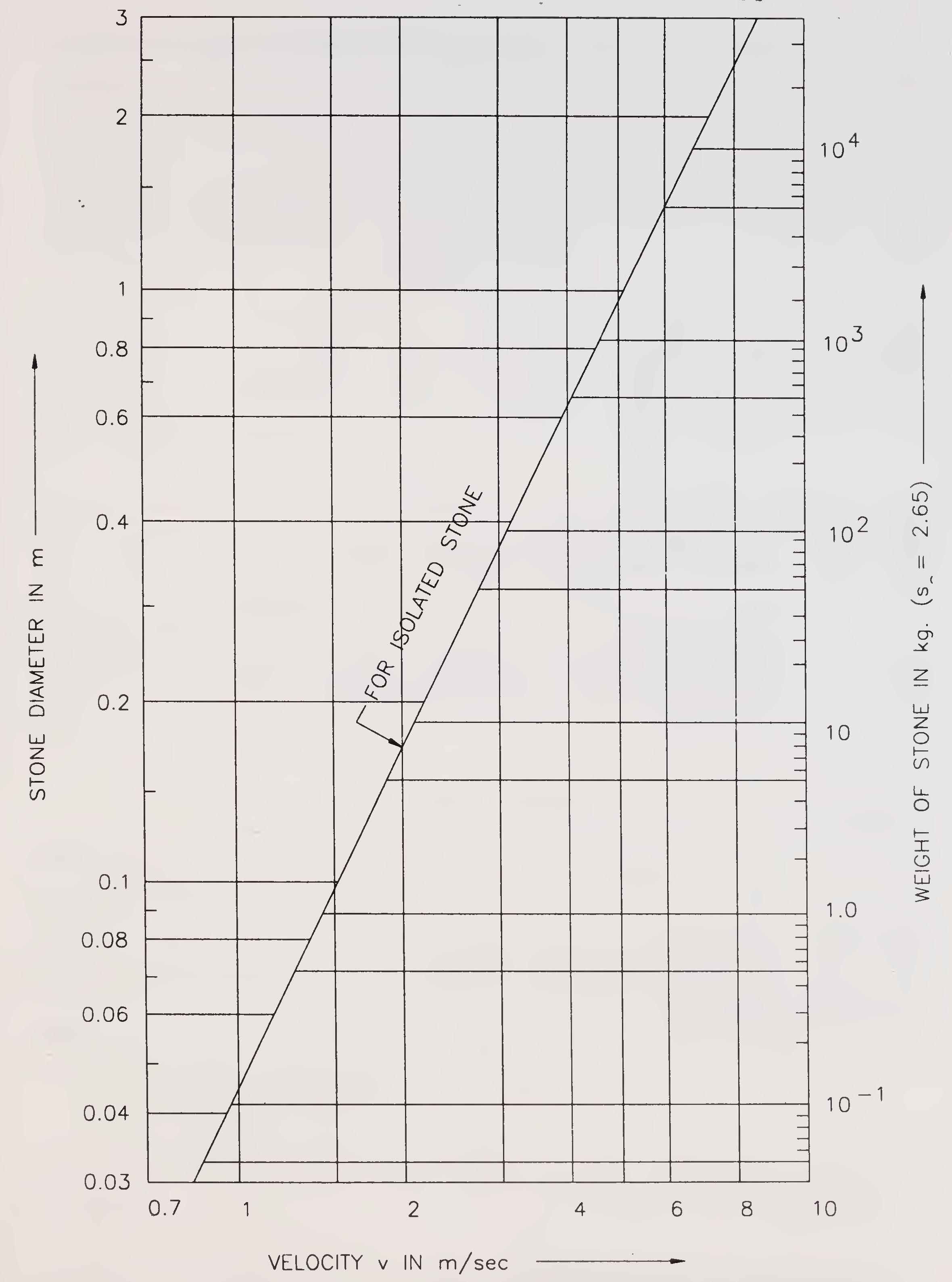
Fig. 5.8. Size of apron stone versus velocity
(Para 5.3.7.2.)23
For velocities upto 5.0 m/sec., the size and weight of stone is also given in Table 5.2.
| Mean design velocity m/sec. | Minimum size and weight of stone | ||
|---|---|---|---|
| Diameter (cm) | Weight (kg) | ||
| upto | 2.5 | 30 | 40 |
| 3.0 | 38 | 76 | |
| 3.5 | 51 | 184 | |
| 4.0 | 67 | 417 | |
| 4.5 | 85 | 852 | |
| 5.0 | 104 | 1561 | |
Notes
|
|||
The extent of scour depends on angle of attack, discharge intensity, duration of flood and silt concentration. It is important that maximum probable depth of scour should be assessed as realistically as possible. The depth of scour for different portions of guide bunds may be adopted as under:
| Location | Maximum scour depth to be adopted |
| Upstream curved mole head of guide bund | 2-2.5dsm |
| Straight reach of guide bund including tail on the downstream of guide bund | 1.5dsm |
|
Where dsm is the mean depth of scour.24 |
It has been observed that shallow and wide aprons launch evenly if the scour takes place rapidly. If the scour takes place gradual, the effect of width on launching of apron is marginal. A width of launching apron equal to 1.5 dmax is generally found satisfactory (where dmax is the maximum anticipated scour depth below bed level in meters). Thickness of launching apron at inner end may be kept as 1.5 t and at outer end 2.25 t as shown in Fig. 5.9.
When stones in wire crates are used the width of launching apron equal to 2.25 dmax for slope of 2:1 and 3.20 dmax for slope of 3:1 may be used. However, the thickness of launching apron may be kept same as that of thickness of pitching (t).
The slope of the launching apron may be taken as 2 (Η): 1 (V) for loose boulders or stones and 1.5 (Η): 1 (V) for cement concrete blocks or stones in wire crates.
An apron may fail to provide protection to the guide bund if the river bed contains high percentage of silt or clay or where the angle of repose of the bed material is steeper than that of stone as in such a case the apron may not launch properly.
Certain types of kankar blocks develop cementing action under water and such types of kankar blocks may be used with caution.
Co-ordination is necessary for tagging together guide bunds of road and rail bridges on the same river or streams where located in close vicinity of each other is likely to be influencing one or the other and for the same appropriate combined, if necessary, hydraulic model studies for both should be carried out to evolve properly tagging design.
Trial pits should be taken in borrow area to examine suitability of soil for construction and also to decide the type of earth moving machinery to be arranged.
Guide bunds may be made of locally available materials from the river bed preferably cohesionless materials. Low density cohesionless soils (loamy soils) are susceptible to liquifaction and should be avoided.
Every effort should be made to complete the work of guide bund in one working season.25
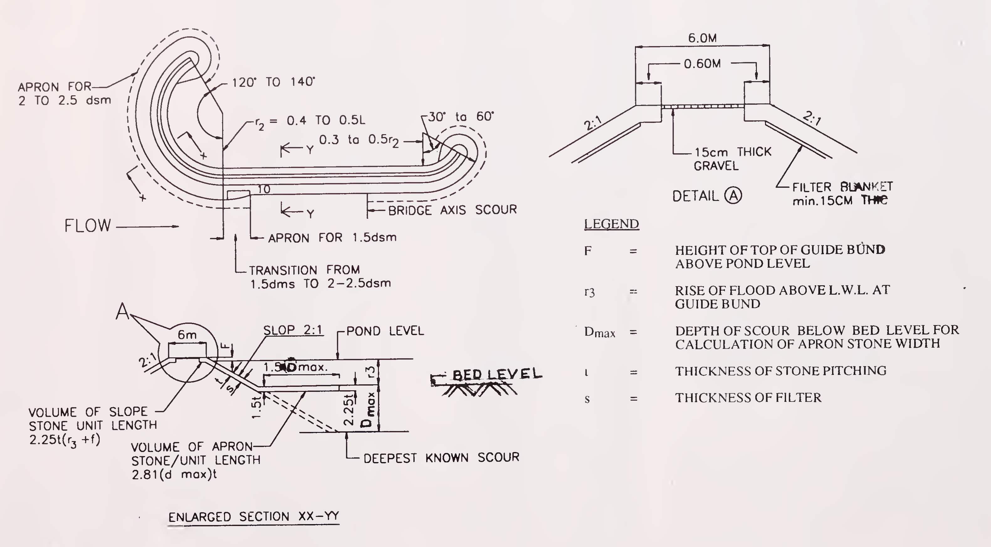
Fig. 5.9. Details of guide bunds
(Para 5.3.7.5)26
For the construction of embankments for guide bunds IRC: 36 “Recommended Practice for the Construction of Earth Embankments for Road Works’’ shall be followed unless otherwise stated in these guidelines. For high embankments IRC: 75 “Guidelines for the Design of High Embankments’’ may be followed.
Transport of stone from the quarries to the river bank and from the river bank to the site of work is an important task. The quantities of stone required to be transported every day must be worked out and trains/ trucks, etc., arranged accordingly. Similarly prior arrangements may be made for taking the stones across the river by ferry or boats.
For construction of guide bunds, four operations are involved:
It is necessary that sufficient length of pit along the guide bund should be ready within one or two months of commencement of work so that placing of stones in the apron and on slope can be started at the earliest. About 70 per cent working season should be available for pitching. Earthwork should be completed within 80 per cent of working season. Good compaction of guide bunds is necessary as any slip during the flood can be disastrous. No portion of the guide bund should be left below HFL before the onset of monsoon. Bottom of apron pit should be excavated as low as permitted by water level.
Sufficient labour and/or earth moving machinery of the right type with spare parts and trained staff is necessary.
No borrow pits should be dug on the rear of guide bunds. It is preferable to take all earth for construction of the guide bunds27
from the river side. The borrow pits should be sufficiently away from the location of the launching apron.
Adequate labour for unloading of pitching stone, carrying and laying it at site within the time available will have to be carefully worked out.
Construction of guide bunds should be taken in hand along with piers and abutments. Where there is any doubt about completion of whole guide bund within one working season, it is absolutely essential that the construction of guide bund be started from abutment towards upstream. Where full guide bund cannot be constructed in one working season suitable protective measures may be taken.
On slopes, care should be taken in placing the stone not to have big voids through which water will cause swirling. Comparatively smaller stones should be at the bottom and larger ones at the top.
The top of the guide bunds should be protected with a layer of 15 cm thick gravel against rain cuts.
While on river side, stone protection is provided upto the full length of guide bunds, on the rear side this protection is just carried around mole head beyond which usually good turfing is provided.
In case the alignment of guide bund or the approach embankment crosses a branch channel of the river, the usual practice under such circumstances is either to divert the branch channel to the main channel of the river with the help of spurs, etc., or to construct closing dyke or closure bund across the branch channel. In situations where diversion of channel is to be resorted to, then action in this regard should be taken during the receding floods and at least 2 to 3 months in advance of the construction of guide bund/ embankment. In situations where closing of the branch channel is considered unavoidable, then the closure bund closing dyke or the armouring of the approach embankment should be properly designed and closing operation should be carried out as a continuous one.28
Spurs are provided to take care of one or more of the following functions:
Spurs can be classified as follows:
Permeable spurs obstruct flow and slacken it to cause deposition of sediment carried by the streams. These are, therefore, best suited for sediment carrying streams and are also preferable in hilly regions.
In comparatively clear rivers their action results in damping erosive effect of the current and thus prevent, local bank erosion.
Impermeable spurs consist of rockfill or earth core armoured with resistant material like stone mattress29
Fig. 6.1. Types of spurs or groynes (Para 6.1.2. (iii) & (iv))
or sausages filled with stone. They are designed to attract, repel or deflect the flow away from the bank along a desired course.
A submersible spur is the one whose top level is above the normal water level in the river but gets submerged during the highest design floods.
This is the type of spur which remains above water even under the highest floods.30
These are the spurs which attract flow towards the bank and are aligned in a direction pointing downstream. In a river where there is a heavy attack on one bank, it may be desirable to construct the attracting spurs on the opposite bank in conjunction with a repelling spur on the affected bank.
A spur pointing upstream has the property of repelling the river flow away from it and hence it is termed as repelling spur.
Where the spur, usually of short length changes only the direction of flow without repelling it, is known as a deflecting spur and gives only local protection.
The spurs located at right angles to the river flow fall under this category.
These spurs have been named after their builders and have special design features like Denhey’s T Headed, Hockey or Burma type and kinked type, etc. A spur with a curved head is known as a Hockey or Burma type spur whereas a spur with a short straight head normal to spur direction is known as a Denhey’s T Headed spur and a spur with a slight angular head is known as a kinked type spur.
No general rule can be laid for fixing the length and location of the spurs. Those depend entirely upon the exigencies arising in a specific case. Length should not be shorter than that required to keep the scour hole formed at the nose away from the bank. Short length may also cause bank erosion upstream of the spur whereas too long a spur may dam up the river. Normally spur should not obstruct more than 20 per cent of the channel width at ordinary flood level.
For repelling spur (defined in clause 6.1.2.6) the angle upstream varies from 60° to 80° with the bank. In the case of attracting spur (defined in clause 6.1.2.5) the angle is usually 60° (within a range of 30° to 60° with the bank. Orientation for deflecting spur (defined in clause 6.1.2.7) can vary from 65° to 85°.31
In a straight reach the spacing is about three times the length of spur. Spurs are spaced further apart (with respect to their length) in a wide river than in a narrow one, if their discharges are nearly equal. In a curved reach a spacing of 2 to 3.5 times the length of spur is recommended. Larger spacing (3 to 3.5 times) can be adopted for concave banks and smaller spacings (2 to 3 times) can be adopted for convex banks. Sometimes the spurs are spaced further apart from consideration of cost or for enabling construction of more spurs at a later date.
Location, length, orientation and spacing can best be finalized from model tests.
The top width of spur should be 3 to 6 m at formation level.
The minimum free board above the recorded highest flood level (H.F.L.) or above the anticipated H.F.L. on the upstream of spur, whichever is more is generally kept as 1.5 to 1.8 m.
For cohesionless soils, slopes on upstream and downstream faces of 2 (Η): 1 (V) may be adequate. For spurs constructed wholly in stones steeper slopes may be adopted.
Same as for guide bunds (see para 5.3.5.1).
Same as for guide bunds (see para 5.3.5.2).
The thickness ‘t’ of the pitching should be provided in a length of 30 to 45m or for such a length of upstream shank upto which the river action prevails (whichever is more) and the semi-circular nose. In the next 30m to 60m the thickness of pitching may be reduced to 2/3t on upstream and in rest of the shank length 0.3 m thick stone pitching may be provided. On the downstream the thickness of pitching may be reduced to 2/3t in 30 m to 60 m and in rest of the shank length a nominal stone pitching or turfing may be provided.32
A graded filter 20 cm to 30 cm in thickness generally satisfying the criteria mentioned in guide bunds (see para 5.3.6) should be provided below the pitching at nose and on the upstream face in a length of 30 to 45 m. In the next 30 to 60 m of the upstream shank portion the filter can be reduced to 15 cm and then filter may be eliminated.
Same as for guide bunds (see para 5.3.7.2).
The depth of scour for different portions of spur can be adopted as given in Table 6.1 and shown in Fig. 6.2.
| S.No. | Location | Maximum scour depth to be adopted |
|---|---|---|
| (i) | Nose | 2.0 dsm to 2.5 dsm |
| (ii) | Transition from nose to shank and first 30 to 60 m in upstream | 1.5dsm |
| (iii) | Next 30 to 60 m in upstream |
1.27 dsm |
| (iv) | Transition from nose to shank and first 15 to 30 m on downstream | 1.27 dsm |
Where dsm is the mean depth of scour measured below highest flood level (HFL)
Fig. 6.2. Plan showing depth of scour for spurs (Para 6.3.7.2)33
A width of launching apron equal to 1.5 dmax (where dmax is the maximum anticipated scour depth below low water level in metres) should be provided at semi-circular nose and should continue upto 60 to 90 m on the upstream or for such a length of upstream shank upto which the river action prevails (whichever is more). In the next 30 to 60 m on the upstream the width of launching apron may be reduced to 1.0 dmax. In the remaining reach, nominal apron or no apron may be provided depending upon the flow conditions. The width of the launching apron on the downstream should be reduced from 1.5 dmax to 1.0 dmax in 15 to 30 m and should continue in next 15 to 30 m. If the return flow prevails beyond the above specified reaches, the apron length may be increased to cover the region of return flow. Thickness of launching apron at inner end may be kept as 1.5 t and at outer end as 2.25 t. A typical design of spur is illustrated in Fig.6.3.
Same as for Guide Bunds (see para 5.3.7.6).
Alternatively, spurs can also be designed with the help of polar diagrams discussed in para 8.
The objects of the tree spurs are to:
Initially, the tree spurs should be laid pointing upstream at an angle between 60° to 70° so that when the spur launches and becomes sand bound, it assumes a position facing slightly upstream. Unlike an impermeable spur, which is generally made to face 60° upstream, a permeable spur should make a larger angle with the bank upstream, since it would collect floating debris against the face, converting it to an almost34
Fig. 6.3. Typical design of spur (Para 6.3.7.3.)35
impermeable one with attendant disadvantages. Care should be taken that after launching, it is not bodily shifted to assume a position of an attracting spur, which would induce accretion only downstream of it.
Tree spurs consist of a thick wire rope firmly tied at one end to the bank and tied at the other end to a heavy concrete block. Leafy trees with large branches are suspended from the wire rope. Alternatively, the tree spurs are also constructed as detailed below:
Vertical stakes are driven 1.5 to 2.5 m into the river bed at 3 m intervals along the cross section of river (see Fig. 6.4). Each row of such stakes are placed about 9 m apart. These stakes are held in position by diagonal stays and guy ropes secured to strong pegs well embedded in the firm banks. The verticals (stakes) are connected to each other by transverse pieces having holes drilled in them to take the tapered end of intermediate verticals of 75. to 100 mm dia, placed in between the main verticals at 0.3 m centres. The entire structure is made watertight by lining the vertical stakes on their upstream side by bundles of local grass and the space between two such rows of spurs is thickly filled with trees. Holes are drilled 0.3 m up their stem through which a ring is fitted. The trees are held in position by a wire rope 2.5 cm dia attached to the rings, the wire rope being firmly anchored to the bank.
However, generally tree spurs are cumbersome to construct and have not been found successful except in a few cases.
Spurs of this type can be constructed out of timber, sheet piles or even R.C.C. piles. In pile spurs (see Fig. 6.5) the piles constitute the main verticals: they are driven down 6 to 9 m inside the river bed, 2.4 to 3.0 m apart and in at least 2 similar rows. The rows of verticals are not more than 1.2 to 1.8 m apart. Between the main verticals, there can be two intermediates, embedded at least 1.2 m below the bed. Each row is either closely inter-twined with brush wood branches, going in and out around each vertical or horizontal railings. The upstream row is braced back to the downstream row by transverses and diagonals. Every other main vertical of the rear row has to be strutted. The strut being embedded a minimum of 2.4 m below bed. Betweeen the two rows, the36
Fig. 6.4. Tree spurs (Para 6.4.1.2.)37
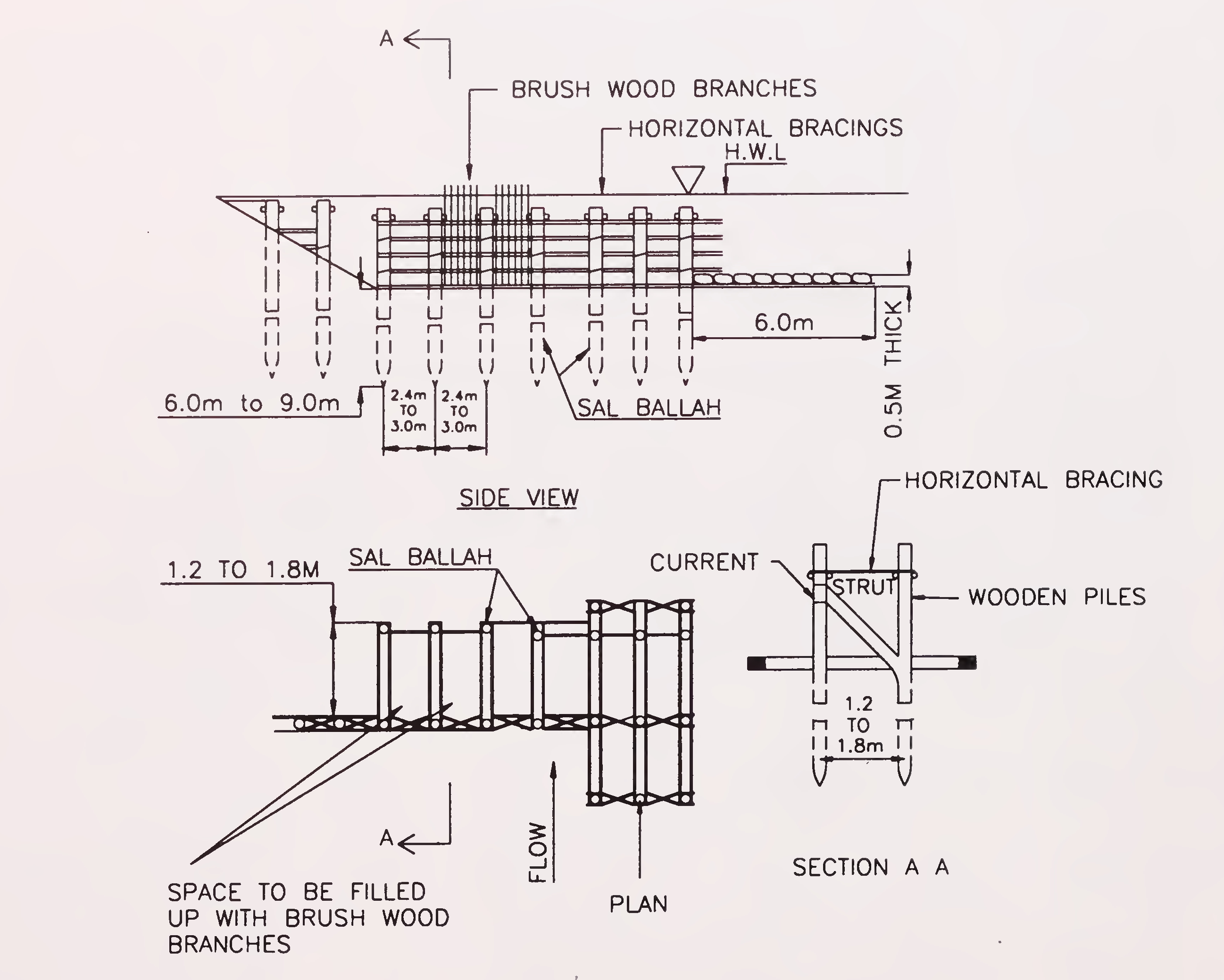
Fig. 6.5. Pile spurs (Para 6.4.2.)38
space is filled with brush-wood branches, closely packed and tamped. The filling may comprise alternate layers of 1.8 m thick brush wood weighted down by 0.6 m thick stones and sand bags. However, debris collects upstream and the spur becomes sand bound and functions subsequently, like and impermeable spur. To guard against scour occurring under such conditions, it is desirable to protect the bed, both up-stream and downstream of the spur and around the nose with a stone apron, 0.9 m thick, 3 m wide along the shank and 6 m wide around nose.
Normally river bank protection is the prime responsibility of flood control authorities. However, for protection of a road embankment running along a river course or for protection of bridge abutment close to the river edge, bank protection measures are sometimes required to be adopted.
For the purpose of design of bank protection, the causes of bank failure have first to be identified as listed below:
Spurs, porcupines, bed bars and studs/ dampeners.
These have been discussed in great detail in Chapter 6.39
These are one particular type of permeable groynes which help to induce siltation along the banks. These are made of steel, bamboo or timber and are provided on a scouring bank in a line normal to the flow. These spurs increase the roughness of the channel thereby deflecting the eroding current away from the bank. In course of time, vegetation grows within the jacks and action of spur is enhanced further.
One type of porcupine, known as Kellner Jack comprises three steel angles about 5 m long bolted together at the centre with the wire string between the legs. A typical unit of porcupine looking from the bank is shown in Fig. 7.1 (a).
Other type of porcupine used for similar purpose is made of bamboo. These are made of 3 to 6 m long bamboo of 75 mm diameter tied together at the centre in the form of a space angle and are weighed down by tying boulder stones packed in wire cage at the centre. A typical bamboo type porcupine spur is shown in Fig.7.1 (b).
Bed bars are submerged structures which help to divide the flow horizontally. Flow above the top of the bed bars can be compared to flow over the submerged weir while flow below the top level of the bar is obstructed by it and is directed towards the nose as in the case of a full height spur. When the alignment of a bed bar is skewed, a pressure gradient is set up. The bed bars can be placed either facing towards upstream of the direction of flow or facing towards downstream of the flow direction.
When the bed bar is facing towards upstream of the flow, the pressure gradient developed helps to deposit sediment on the upstream side of the bar and thus is useful for bank protection. This is shown in Fig. 7.2(a).
When the bed bar is facing towards downstream of the flow, the pressure gradient directs the bottom current away from the bank while surface flow is directed towards the bank. This is provided upstream of an offtake point for sediment exclusion and is shown in Fig. 7.2(b).40
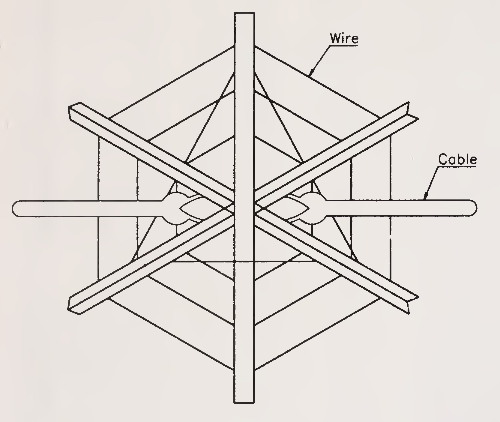
Fig. 7.1 (a): Steel Jetty-Kellner Jack
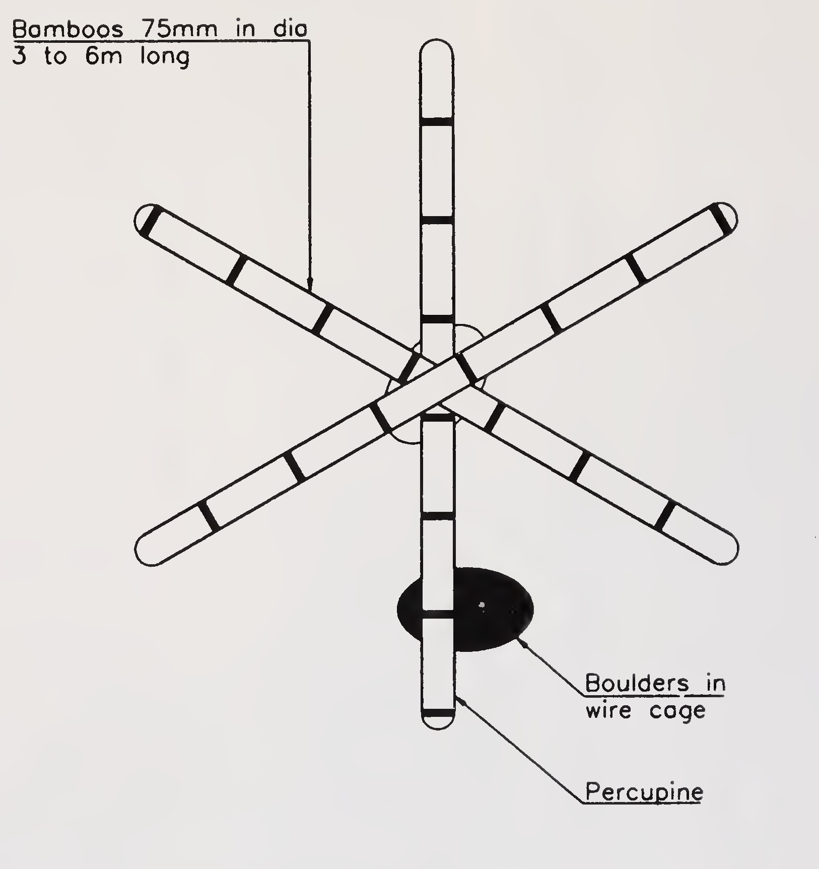
Fig. 7.1. (b): Porcupine spur (Para 7.2.1.2.)41
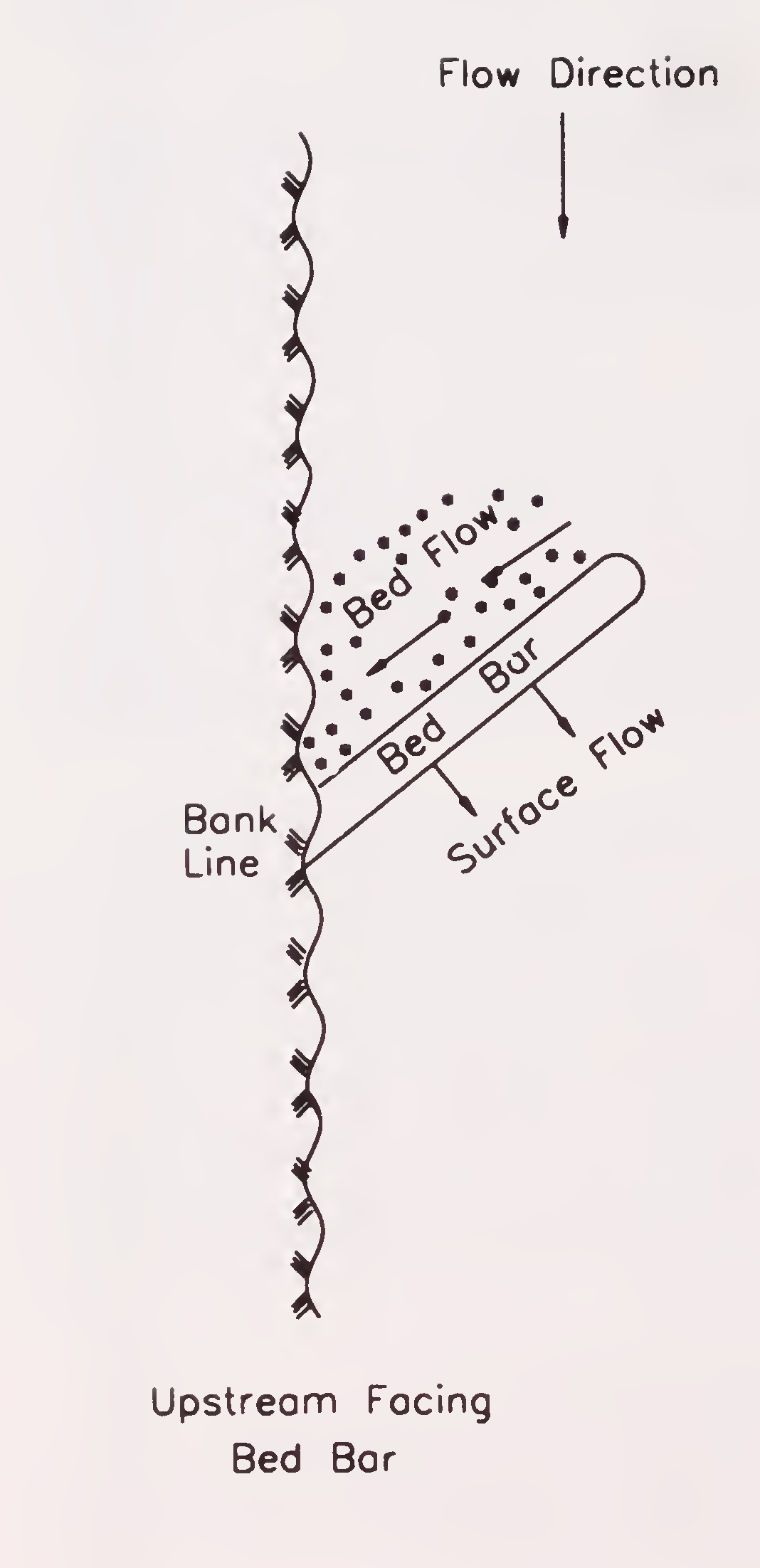
Fig. 7.2 (a): Upstream facing bed bar
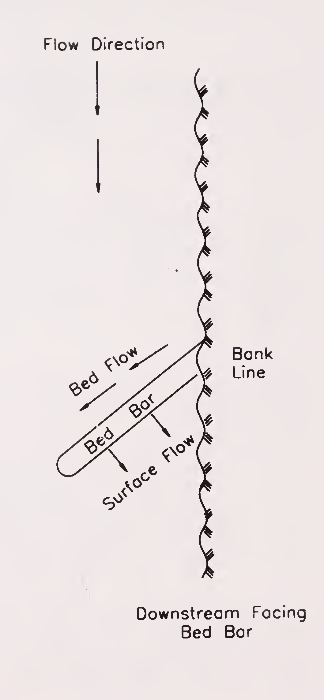
Fig. 7.2 (b): Downstream facing bed bar (Para 7.2.1.3.)42
These are short spurs provided between the regular long spurs to provide local protection to the river bank. Thus the studs are useful device of bank protection where embayments occur between the T-head groynes. A typical design of stud is given in Fig. 7.3.
Stone or concrete block revetment with properly designed launching apron.
Before undertaking the work of permanent river bank protection, some sort of temporary protection work must be done near the abutments of the bridges located on the downstream. Only after observing the behaviour of the river for sometimes permanent river bank protection works should be taken up.
Trees, brushwood, grass, etc., have to be removed both above and below the water level for clearing the bank. The cleared bank slope has then to be graded so that it is flatter or at least equal to the angle of repose of the soil under water so as to prevent sloughing. The landside slope of the pitched bank made in the form of an embankment should be flat enough to be stable. The top width of the embankment may be at least 1.5 m.
A minimum free board of 1.5 m above HFL is generally provided.
Same as for guide bunds (see para 5.3.5).
Same as for guide bunds (see para 5.3.6).
As the attracting influence of the pitched bank depends on the extent to which scour occurs at its toe, the revetment has to be provided with elaborate toe protection in the form of launching apron. The apron has to be designed for the maximum depth of scour likely to occur. Generally, the maximum anticipated depth of scour is assumed to be 1.5 dsm in a straight reach and at a moderate bend where dsm is the mean depth43
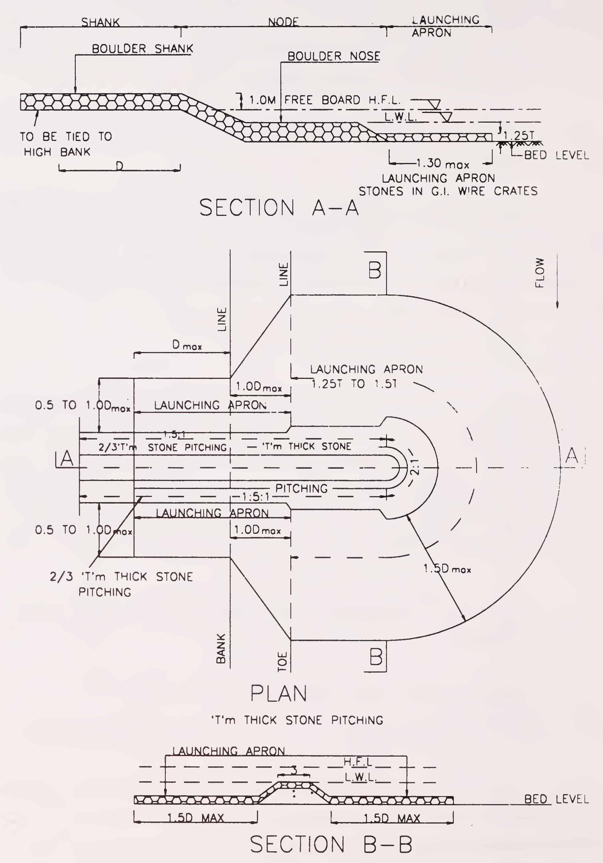
Fig. 7.3. Typical design of stud (Para 7.2.1.4)44
of scour measured below highest flood level to be calculated as per IRC: 5. In the case of bank at severe bend, it is assumed as 1.75 dsm and in the case of bank at right angled bend, it is assumed as 2.00 dsm. The design of launching apron should be made in the same way as for guide bunds (see para 5.3.7.1.).
Nature of protection to be provided for approach embankment of highway bridges depends upon its location which can be divided into the following broad categories:
These cases occur where the river flows through flat terrain with large spills. In such cases, bridges have to be provided with adequate waterway to allow for quick and easy flow of the flood water so as to prevent undue afflux and consequent submergence of valuable agricultural and other lands. Further where the bed material is scourable, flooring with curtain walls is often provided. In case spill-through type abutments are provided in conjunction with the flooring, the sloping embankments in front of the abutments, often extending into the river causing some construction in the flow, need to be adequately protected against the erosive attack of the flow across the embankment.45
Apart from the above, cases may also arise wherein spill-through type abutments may be adopted from economic consideration for bridges with open foundations in non-scourable or rocky bed. In such cases also, the approaches will need to be adequately protected. In either case, the treatment should be on the lines discussed in para 8.2.2.
For a particular bank slope and velocity of flow, the thickness of the slope pitching, size of the stone, its gradation and filter design should be worked out in accordance with the recommendations made in para 5.3. However, the designed values arrived at should not fall below those indicated in Figs. 8.1(A) or 8.1(B).
The slope pitching should terminate either in a short apron at the bed level as indicated in Fig. 8.1(A) or the pitched slope anchored in the flooring/rock as shown in Fig.8.1 (B). However, along the length of the approach, the bank protection should begin and end at a stable section on the approach subject to a minimum of 15 m. In cases where the river banks have to be protected they should also be protected in a similar manner and if such stable sections are not available, suitable terminal treatment of pitching should be provided at the ends as shown in Fig.8.2.
These cases occur where the flow is confined within banks during ordinary floods but spills during high floods without meandering. In such cases, waterways provided are often less than the bank to bank width of the river, which is very wide during high floods and the approaches to the bridges protrude into the river tending to act like spurs. There will be parallel flow with increase in velocity along the embankment. The distance of the embankment so affected depends directly upon the percentage of constriction adopted and the angle of crossing. Large constrictions will not only result in excessive cost of protection consequent to deepening of bed but would also entail deeper foundation of bridges, as well as change in channel profile both upstream and downstream. The final decision as to the percentage of constriction to be adopted should46
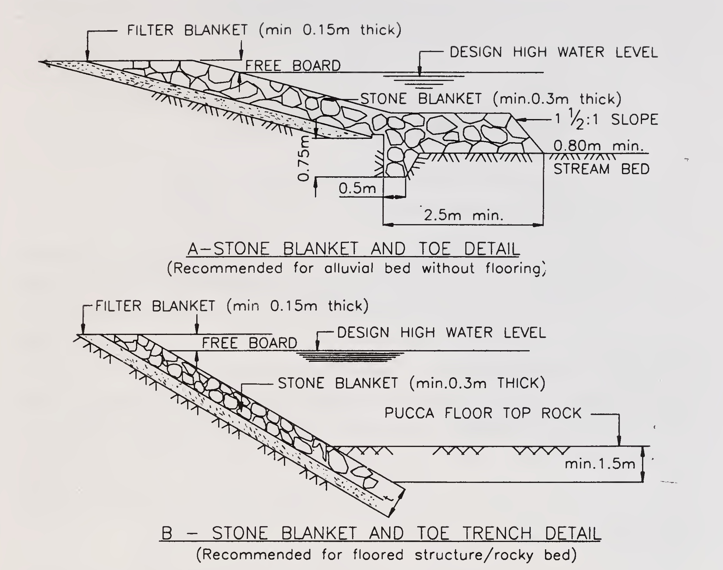
Fig. 8.1. Typical sections of stone slope protection (Para 8.2.2)
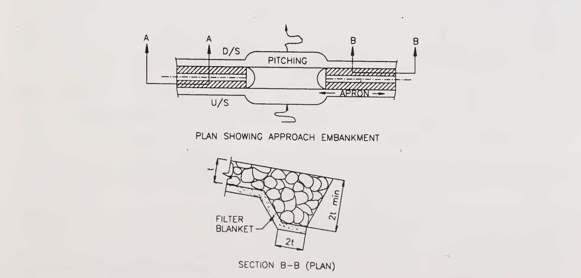
Fig. 8.2. Details of cut-off at terminals of rip-rap blanket (Para 8.2.2.1)47
be such that the cost of the bridge plus the protection to be provided is the minimum. The various parameters that affect the design of protective works of the approaches are as under:
Under the above conditions, the approach embankment protruding into the river is under the direct attack of the river flow and this needs to be protected like a spur. It is seen that the scour reduces as one moves along the spur towards the bank for which the extent of protection could be curtailed towards the bank. The polar diagrams given in Fig. 8.3 show the centre line of spur as base and the ratio of deepest scour depth to mean depth of scour as ordinates. These ratios can be made use of to ascertain the maximum scour depth once the mean depth of scour is known. Thereafter, once the points of deepest scour are known, the apron widths for the approach embankments can be designed in accordance with the provisions contained in para 5.3.
Another aspect is the length along the approach embankments which needs to be protected. The length on the upstream and downstream side of the spurs needing protection bears a linear relationship with the angle of spur as shown in Fig. 8.4. On the analogy of the approach embankments acting as short spurs, the upstream and downstream lengths needing protection may be divided into two categories as shown in Fig. 8.3 viz., category ‘X’ extending from the bank to the point of mean depth of scour and category Ύ’ extending from the point of mean depth of scour to the point of deepest scour towards the deep channel. The portion covered under category ‘Y’ could be assessed based on the corresponding values of the lengths of spurs requiring to be protected, i.e., ‘Lx’ given as fraction of total length ‘L1’ of approach embankment projecting into the river and obtained by taking the angle of spur to the direction of flow and reading the values from Fig. 8.4. The length of the approach L1-Lx gives the length of the approach under category ‘X’. Design of the slope pitching, filter backing and apron under category ‘X’ and category ‘Y’48
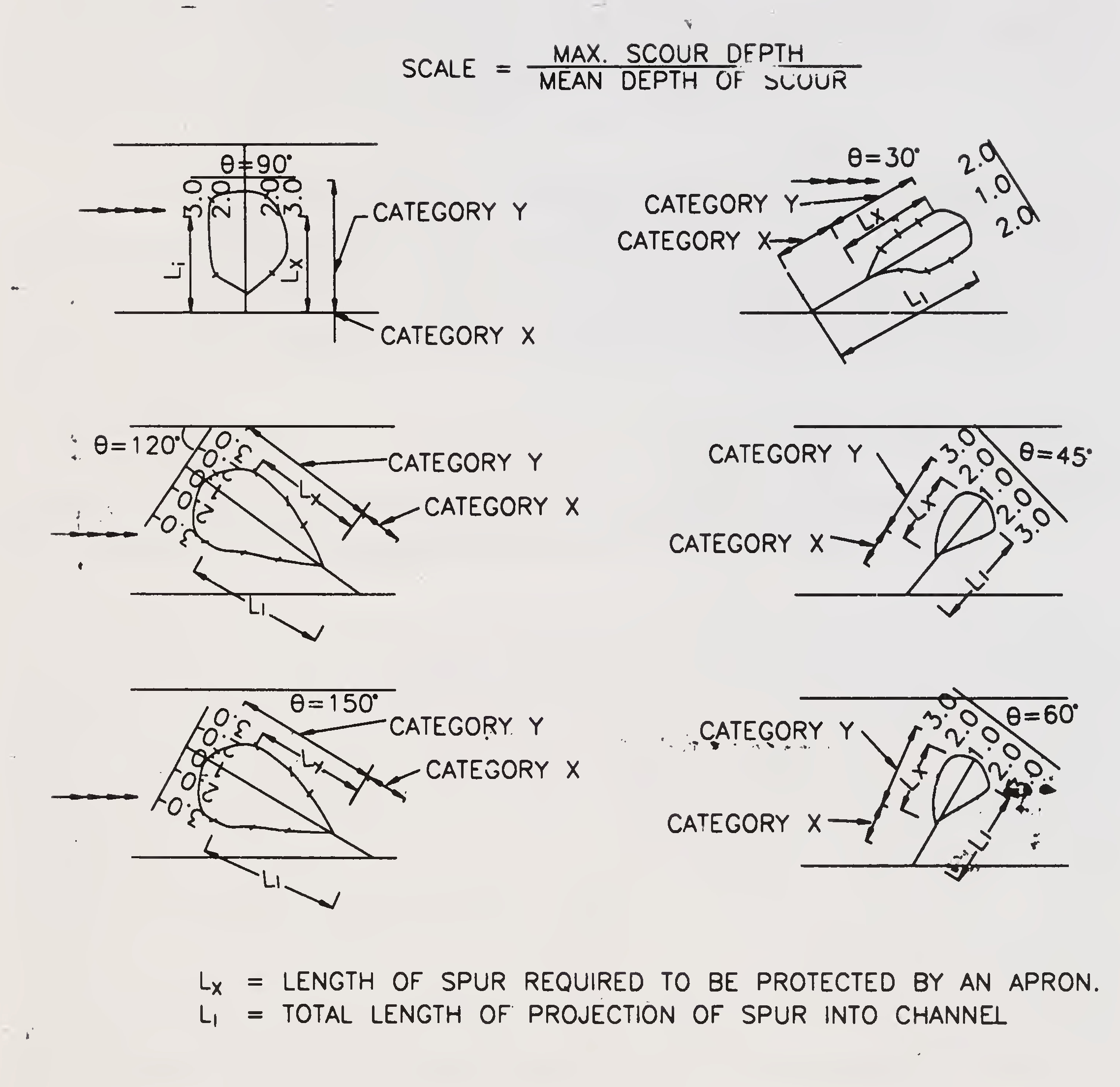
Fig. 8.3. Polar diagram of different inclination of a straight spur showing type and extent of projection (Para 8.3.2.)
could be made on the basis of recommendations given in para 5.3. The apron width for category ‘X’ may be designed as a nominal one and its width reduced uniformly from that required at the end of category ‘Y’ to 2.5 m (minimum).49
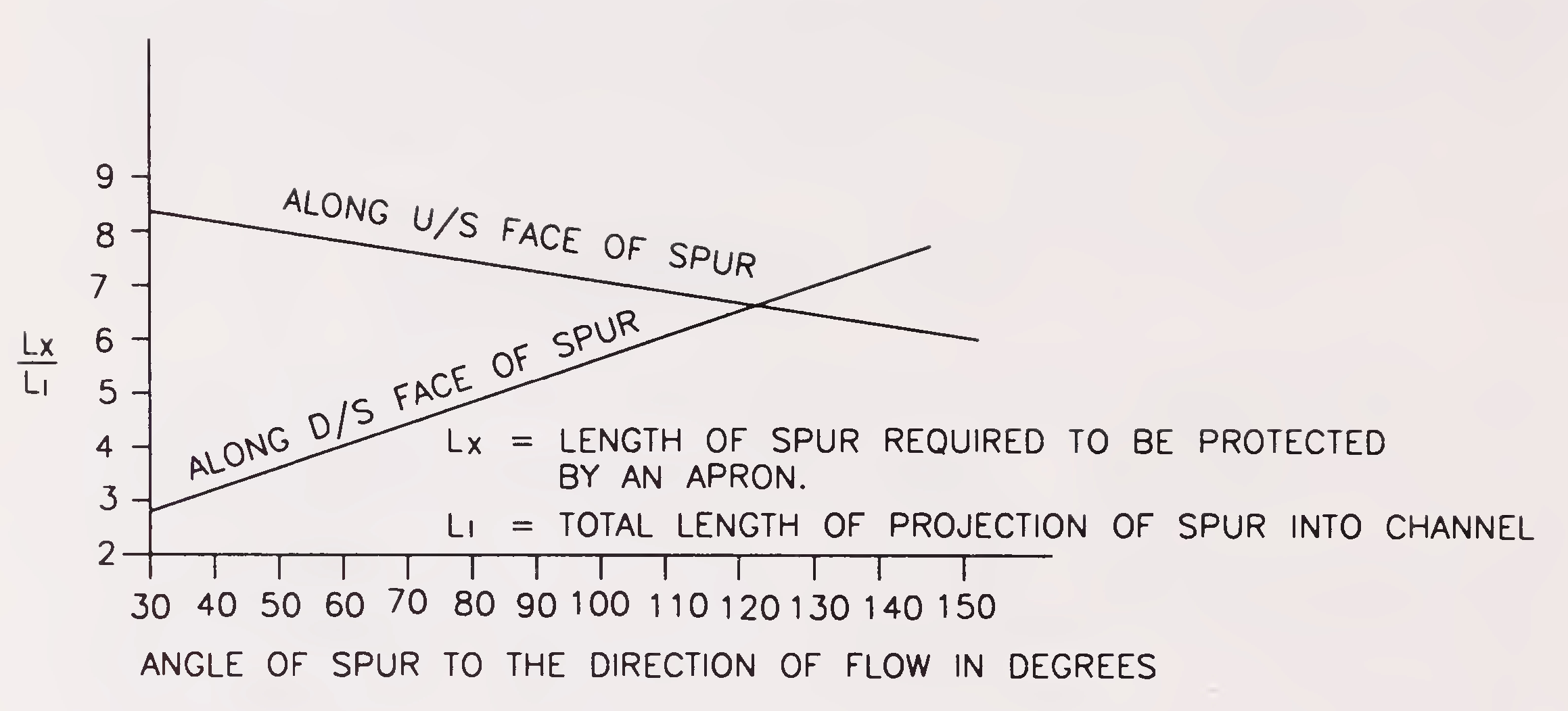
Fig. 8.4. Length requiring protection as a function of the spur inclination (Para 8.3.3.)
These cases pertain to rivers which meander in the alluvial plains and have large Khadir widths even under ordinary flood conditions. From economic considerations, it is, however, imperative to provide waterways much less than the width between ends of the Khadir of the river. This is achieved with the help of guide bunds, the treatment of which has been discussed in para 5, which restrict the river to flow within an artificial gorge. The section of the approach embankment beyond the Khadir portion is subjected to flooding but there is no significant flow to cause scour due to parallel flow or draw down conditions and balancing of water on both sides of the embankment. For these conditions to be satisfied, however, the alignment of the approach embankment and its distance from the worst possible embayment loop should be fixed as indicated in paras 5.2.1.1 and 5.2.3.1 respectively.
In view of still water conditions, nominal slope pitching, e.g., 0.3 m thick may be provided for embankment height upto 7.5 m increased to 0.5 m in the lower portion where its height exceeds 7.5 m. The minimum weight of stones used shall be 40 kg.
The design of filter backing is dependent on the voids in the stone pitching and the gradation of bank material. For the nominal nature of50
pitching suggested in the preceding sub-para, base filter of 150 mm thickness may do.
The slope pitching should extend well above the pond level taking into account the exigencies of abnormal floods and wave action. The free board in any case, should not be less than 1.2 m. A higher free board would be advisable in case of aggrading rivers.
The pitched slopes should be provided with nominal toe protection in view of very little velocity. At any rate, toe walls should be avoided and nominal apron of at least 2.50 m width and 0.50 m thickness should be provided at bed level. No protection of downstream slope is ordinarily necessary and provision of turfing may suffice.
In case other types of pitching and filter materials as well as toe protection measures are required to be adopted as per site conditions, a suitable design as recommended in para 5.3 may be adopted.
For construction of approach embankments within the khadir area no borrow pits shall be permitted within the area bounded by the guide bund on one side, natural bank on the other side and the lines drawn tangentially to the top of upstream and downstream curved heads parallel to approach embankment. Moreover, the edge of the nearest borrow pits shall be not less than 200 metre from the toe of the embankment both on the upstream and downstream side in any case.
As far as possible, no opening should be provided in the bridge approaches falling in the khadir portion of the river. However, if these are unavoidable, only floored structures should be provided with revetment in immediate approaches on either side of the structure. These structures should be provided with sluice gates which should be kept closed during flood season.
Where the approach embankment in the Khadir terminates in a marginal bund or at any protective embankment/afflux bund constructed by irrigation/flood control department, the adequacy of the latter within the zone of influence of embayment should be checked and if need be, the same should be got suitably raised/strengthened in that stretch.51
The aforesaid guidelines do not cover the provision where the approach embankments are under the attack of sea waves or tidal bores, etc. In such cases, the protective measures may be evolved based on expert literature/model experiments. Stability of embankments to be protected should be ensured on the basis of local experience and/or slope stability analysis related to appropriate soil data.
The rivers in sub-montane regions do not present a regular pattern of meanders as in the case of alluvial rivers in plains. The bed slopes of the rivers in the hilly regions are very steep which create tremendous velocities and bed materials being unable to withstand such velocities are scoured and transported down the river. They carry very heavy charge of coarse sand, shingle and boulders, which are accentuated by large slips and landslides that take place in the hill slopes and result in heaps of deposits on flatter slopes. In the North-Eastern part of this country, it is further aggravated by the seismic character of the Himalayan zone. Due to seismic disturbances the friable rock loosens and landslides occur and the sediment load of the Himalayan rivers increases substantially. The channels become shallow and owing to the reduced velocity, obstructions in the form of heaps result in diversion of the channel itself. As the river bed upstream through the bridge itself rises, the flood cannot pass through the bridge quickly and it heads up-above the bridge submerging low lying areas. The bed level of the river upstream of the bridge thus rises progressively with consequent rise in the flood levels resulting in increase in flooding of areas upstream of the bridge. The protection works for submontane regions merit special consideration besides the points already covered in earlier paras. It is, therefore, necessary that protection works for bridges in sub-montane regions are decided judiciously by the Engineer-in-charge keeping in view the site conditions and other relevant factors.
Most of the rivers in sub-montane terrain are subject to the phenomenon of rolling boulders during high floods. Huge boulders hitting52
the piers and abutments may cause enormous damage. In such cases, heavy protection around piers/abutments may be necessary which may be in the form of stone facing or steel plate lining. The same may be decided by the Engineer-in-charge keeping in view the site conditions. In case heavy floating debris is anticipated, necessary traps may be provided to prevent the same from reaching the structure.
Permeable spurs and toe walls with launching apron may also be considered for protection works.
For bridges where adoption of shallow foundations becomes economical by restricting the scour floor protection to bridges has to be provided. The floor protection will comprise of rigid flooring with curtain walls and flexible apron so as to check scour, washing away or disturbance by piping action, etc. Usually performance of similar existing works is the best guide for finalizing the design of new works. However, the following minimum specification for floor protection shall at least be followed while designing new structures subject to the general stipulation that post protection works velocity under the structure does not exceed 2 m/s and the intensity of discharge is limited to 3 m3/m.
Excavation for laying foundation and protection works shall be carried out as per specifications under proper supervision. Before laying the foundation and protection works the excavated trench shall be thoroughly inspected by the Engineer-in-charge to ensure that:
The rigid flooring shall be provided under the bridge and it shall extend for a distance of at least 3 m on upstream side and 5 m on down stream side of the bridge. However, in case the splayed53
wing walls of the structure are likely to be longer the flooring shall extend upto the line connecting the end of wing walls on either side of the bridge.
The top of flooring shall be kept 300 mm below the lowest bed level.
Flooring shall consist of 150 mm thick flat stone/bricks on edge in cement mortar 1:3 laid over 300 mm thick cement concrete M-15 grade laid over a layer of 150 mm thick cement concrete M-10 grade. Joints at suitable spacings (say 20 m) may be provided.
The rigid flooring shall be enclosed by curtain walls (tied to the wing walls) with a minimum depth below floor level of 2 m on upstream side and 2.5 m on downstream side. The curtain wall shall be in cement concrete M-10 grade/brick/stone masonry in cement mortar 1:3. The rigid flooring shall be continued over the top width or curtain walls.
Flexible apron 1 m thick comprising loose stone boulders (weighing not less than 40 Kg) shall be provided beyond the curtain walls for a minimum distance of 3 m on upstream side and 6 m on downstream side. Where required size stones are not economically available, cement concrete blocks or stones in wire crates may be used in place of isolated stones.
Wherever scour is restricted by provision of flooring/flexible apron, the work of flooring/apron etc., should be simultaneously completed alongwith the work on foundations so that the foundation work completed and left to itself is not endangered.
The river has its own peculiarities depending on its size, load characteristics, the terrain through which it flows and the nature of the54
banks. Hence, each case is to be considered individually. In spite of our efforts to improve the design, we are still to go a long way before understanding the absolute truth of nature and till then one has to cater for unknown parameters with a factor of safety. It is here that model studies offer a handy tool at supplementing the work of designer and by providing an insight into conditions likely to obtain in the prototype.
River flow being a very complex phenomenon, eludes easy analysis in many cases. This is more so in the case of bridges on the alluvial rivers where normal river waterway is constricted. In some cases where the bridges are not located on the straight reaches or where it is required to study the effects of other structures viz., an existing bridge, a weir, a new dam or flood embankments or ghats along the river, it is not possible to visualise the river behaviour accurately in respect of flow pattern, discharge distribution, etc., after the construction of the structure. In all such cases, model studies will be helpful.
In cases where the cost of a new bridge project or additional river training works for existing bridge is substantial, model studies are advisable. Model studies in such cases cost a very insignificant percentage of the total cost of project and have the added advantage of suggesting improvements which may sometimes lead to reduction in the cost of the structure.
The importance of the bridge viz., its location on strategic routes or its proximity to major industrial complexes, towns, etc. is yet another consideration for resorting to model studies.
In the situations warranting model studies mathematical model studies may also be carried out as per guidelines indicated in Appendix-3.
Model studies may be required for one or more design aspects55
as mentioned below.
Selection of suitable site and alignment of bridge in relation to river configuration and flow.
Adequacy of bridge waterway in relation to velocities, flow distribution, afflux and location of guide bunds.
Works like spurs, bank pitching etc., required if any, upstream or downstream sides of the bridge.
Afflux at the bridge piers, scour around the piers and at the river bed and related protective measures.
To study the effects of existing or future structures like dams, ghats, spurs, embankments, etc., on bridges.
The following details including ground survey, hydraulic and sediment data are required for model studies.
This should include :
Note: All levels shall be connected to the G.T.S. Bench Mark.
Note: All gauge and discharge sites should coincide with cross sections and should be marked on survey plan referred to in para 11.4.2(2).
Suspended sediment data may be collected using suitable samplers near the central gauge station in the reach. Samples should be collected at medium and high flood stages. Samples may be analysed to estimate percentage of coarse, medium and fine fractions.
Note: Position of bed-bank material samples, bore-holes and sampling particles should be marked on survey plan referred to in para 11.4.2(2).
While some type of problems can be solved with the aid of model studies with a high degree of accuracy, certain aspects of studies connected with the rivers flowing in alluvium present difficulties. In the mobile bed river models, the results lack scalar transformation to the prototype. They cannot, therefore, be applied quantitatively but can be regarded as qualitative. Some of these aspects are described in Appendix-4. Suitable model techniques have been devised to reduce the gap between model results and natural occurrence showing what may be reasonably expected from the model results and what should not be expected. Models are always helpful in that, they make it easier to visualise the problems and evaluate the relative affects of different treatments making allowance for model limitations, but the success depends primarily on correct diagnosis and evaluation of all factors causing change.
In the final analysis, the validity of results of model study and interpretation of its results depends on experience, sound judgement and reasoning of the experimenter.
The successful functioning of any river training and protective work depends to a great extent on its proper design, construction and maintenance. After completion of river training and protective works, a close watch must be kept on their performance so that timely action, wherever necessary, can be taken to avoid major damages and difficulties at a later date.60
The protective works like guide bunds spurs, pitching around abutments, etc., shall be inspected.
The inspection before the floods shall be carried out to ensure that all flood protection measures have been carried out as per design in case of new works. In case of existing works it will be ensured that these are intact and in position as per design and drawings.
Inspection during the floods shall be carried out to have information about HFL obtained, scouring of bed, and launching of apron etc., so as to take corrective measures as soon as required. The inspecting officer must look for aspects like launching of the apron, settling of the slopes, piping action, improper drainage of the rain water causing the slope to be disturbed, impact of waves, carrying away of the smaller particles and thus disturbing the slope, any undue scour at the nose of the bund and/ or at the toe of the pitching and give his recommendations to ensure that the protective works function adequately. The quantity of reserve stones available at site for meeting emergent situations shall be checked before floods against specified quantity and duly reported.
The floor protection shall also be inspected before, during and after the floods to ascertain the extent of scour, cracking and damage of the floor, if any and adequacy of the cut off walls and apron, etc. Specific recommendations for augmentation of the existing provisions, if any, shall also be given.
Proper maintenance of river training and protective works is extremely important as damages to them can be more dangerous than damages to bridges where no protective works are provided. It is, therefore, important that maintenance Engineers are made aware of the design principles underlying the various provisions made in different protective works as well as likely causes and nature of damages so that their significance is very well understood and the maintenance is carried out effectively. They should also acquaint themselves with the past history of the bridges, their protective works and behaviour of the river as only when they possess all this knowledge that they can deal effectively with any maintenance problem.
Keeping the above in view the list of important records which should be available at site for proper maintenance has been drawn. But this list is by no means exhaustive and other records as necessary in each individual case should also be kept at site.
short grass or both growing on the slopes of embankments is good protection against erosion and wave wash. Generally, the slopes should be turfed with grass sods.
FORMULA FOR COMPUTATION OF AFFLUX
Afflux is approximately calculated using Molesworth formula given below:
Appendix 1(a)
(Para 4.6.3)

Where
*h1 = afflux in metre
V = average velocity of river prior to obstruction in metre sec.
A = unobstructed sectional area of river in sq. metre.
A1 = sectional area of river at obstruction in sq. metre.68
Appendix 1
(Sub-para 4.6.3)
METHOD FOR COMPUTATION OF BACKWATER OR AFFLUX AT BRIDGE PIERS FOR RIVERS CARRYING DISCHARGE MORE THAN 3000 m3/sec.
The profile along the centre of the stream at the bridge site is given in Figs. 1 and 2. The rise in water level above normal water surface at Section 1 due to construction of the bridge is denoted by h*1 and is called the backwater of afflux.
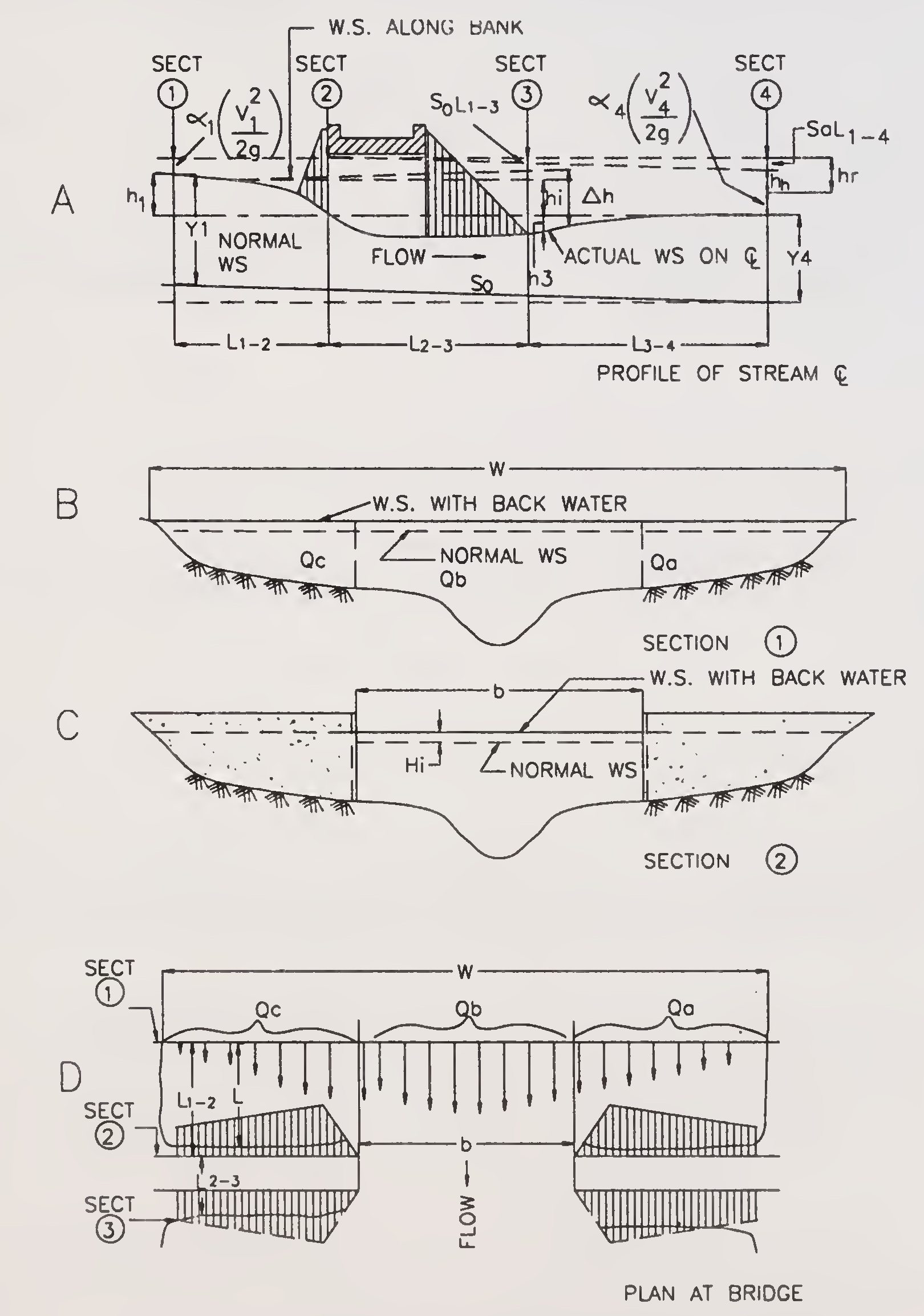
Fig. 1. Normal crossing-wing wall and abutments69
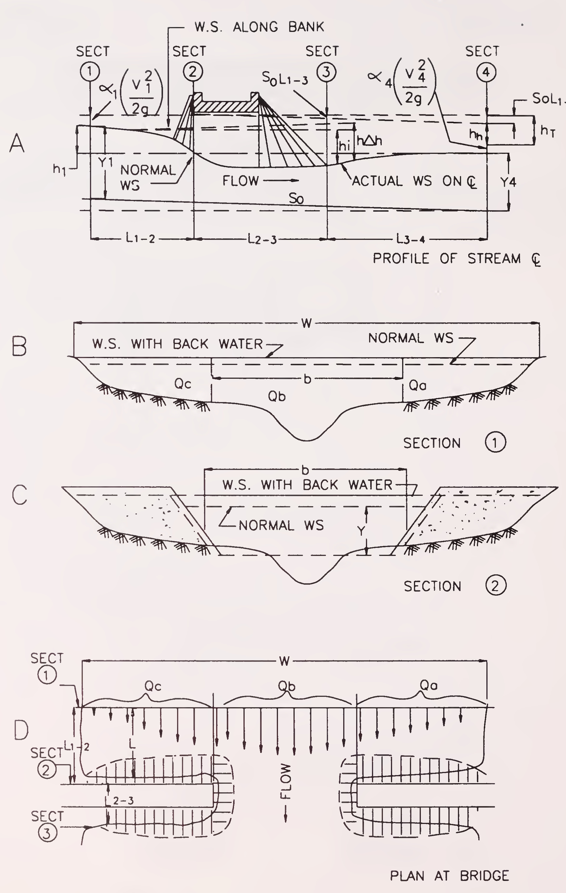
Fig. 2. Normal crossing-spill-through abutments70
A practical expression for backwater has been formulated by applying the principle of conservation of energy between the point of maximum backwater upstream from the bridge Section 1 and a point downstream from the bridge at which normal stage has been re-established in Section 4 (Figs. 1 A and 2 A). The expression is reasonably valid if the channel in the vicinity of the bridge is essentially straight, the cross sectional area of the stream is fairly uniform, the gradient of the bottom is aproximately constant between sections 1 and 4, the flow is free to contract and expand, there is no appreciable scour of the bed in the constriction and the flow is in the sub-critical range.
The expression for computation of backwater h*1 (in FPS units) upstream from a bridge constricting the flow, formulated on the basis of model studies is as follows:

To compute backwater, it is necessary to obtain the approximate value of h*1 by using the first part of expression (1)

The value of A1 in the second part of the expression (1) which depends on h*1 can then be determined and the second terms of expression (1) evaluated.
The value of the overall backwater coefficient K* is dependent on the following:
Kb is the backwater coefficient for a bridge in which only
the bridge opening ratio M is considered. Knowing the type of abutments, shape of wing walls and the value of M, use Fig. 3 for estimating Kb.71
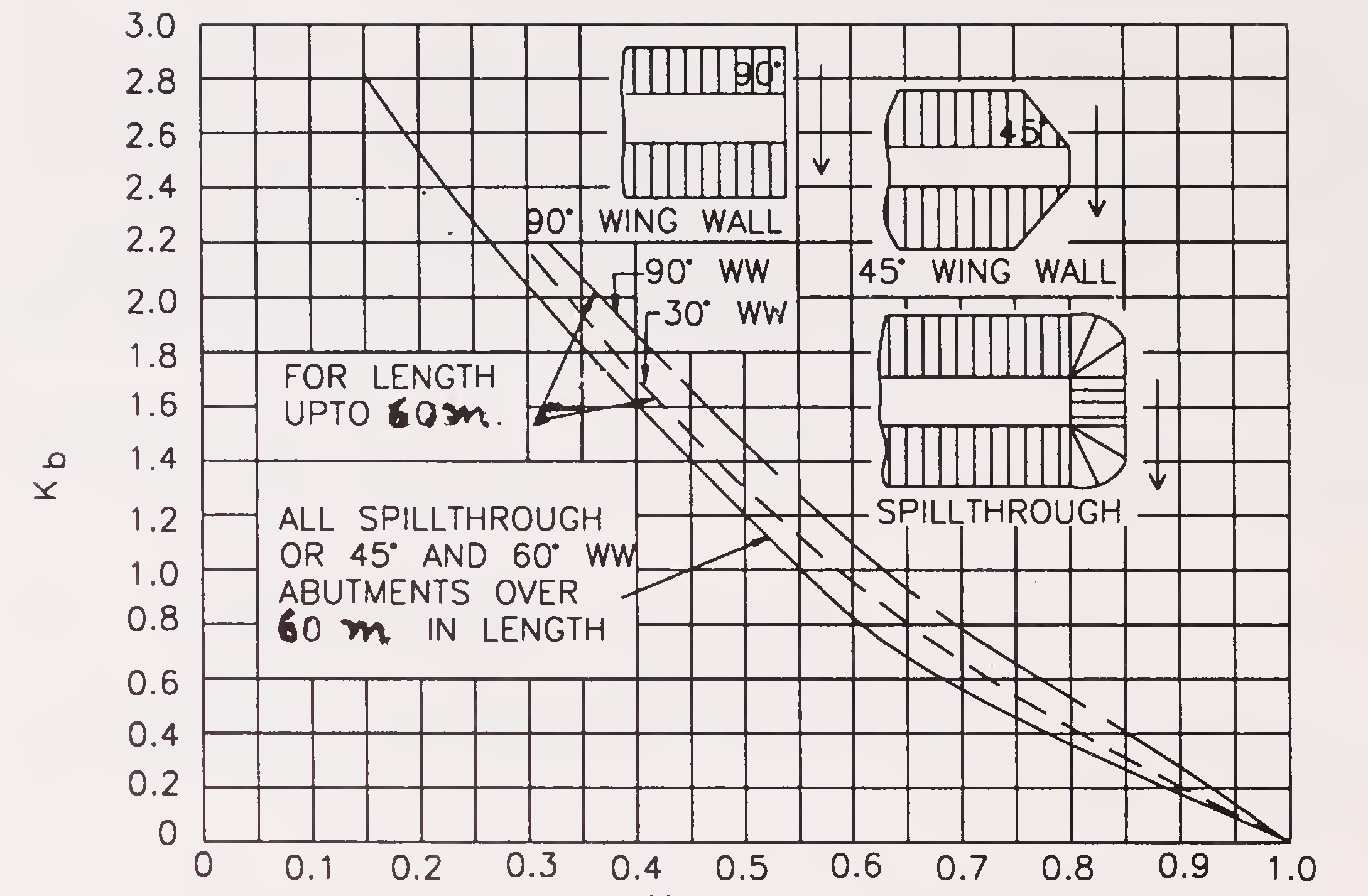
Fig. 3. Backwater coefficient base curves (sub-critical flow)
The introduction of piers in a bridge causes constriction and consequential backwater. This incremental backwater coefficient is designated as Δ Kp, which can be obtained from Fig.4. By entering chart-A with the proper value of J and reading upwards to the proper pier type, Δ K is read from the ordinate. Obtain the correction factor, σ from Chart-B in Fig.4 for opening ratios (M) other than unity. The incremental backwater coefficient is then

In the case of skewed crossings, the effect of piers is calculated as for normal crossings except for the computation of J, An2 and M. The pier area for a skewed crossings Ap is the sum of the individual pier areas normal to the general direction of flow as illustrated in Fig. 4. An2 for a skewed crossing is based on the projected length of the bridge bs cos ϕ and also includes the area occupied by the piers. The value of J is the pier area. Ap, divided by the projected gross area of the bridge constriction, both measured normal to72
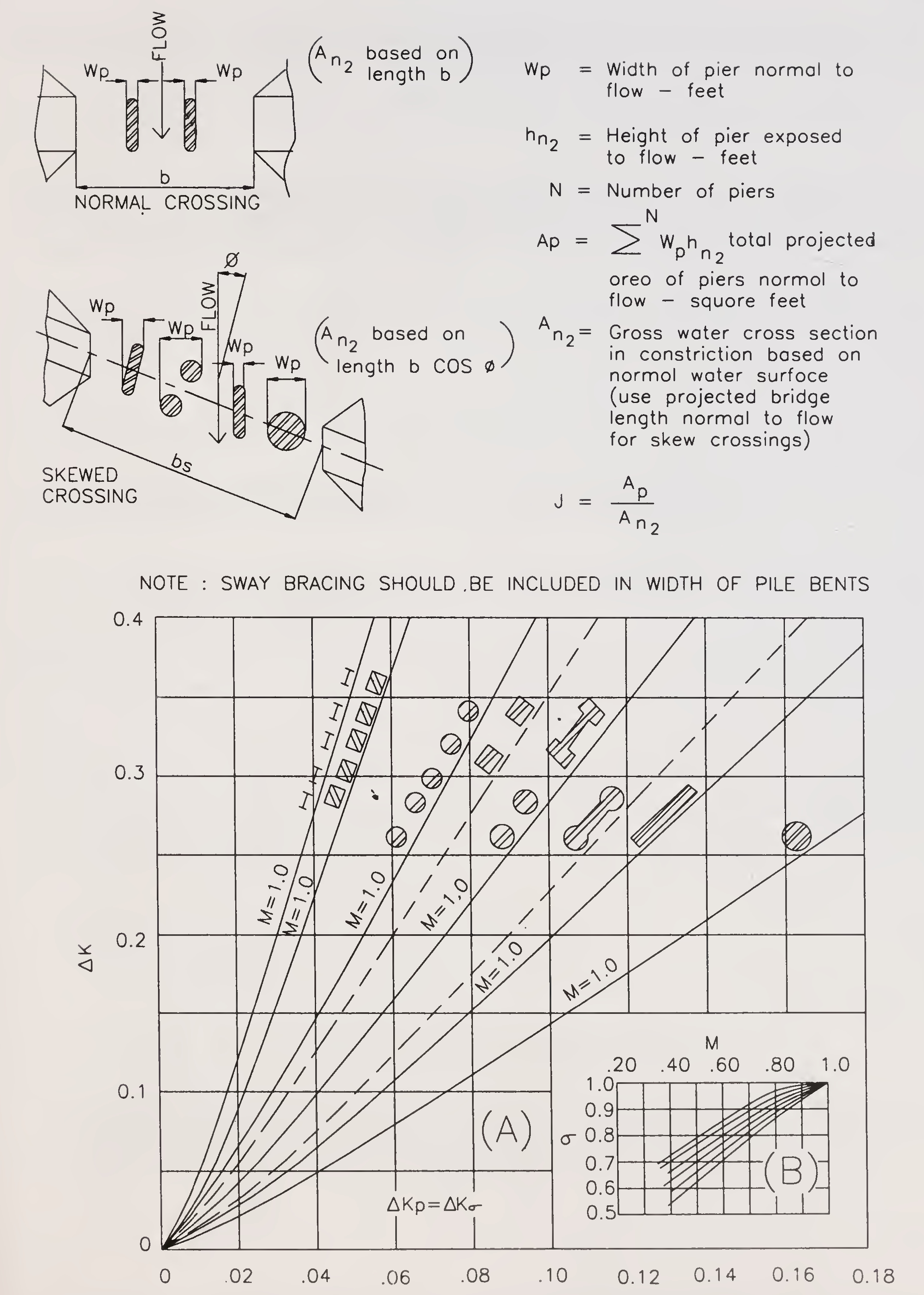
Fig. 4. Incremental backwater coefficient for piers73
the general direction of flow. The computation of M for skewed crossing is also based on the projected length of bridge.
The magnitude of the incremental backwater coefficient Δ Ke accounting for the effect of eccentricity can be calculated from Fig. 5. Eccentricity is defined as 1 minus the ratio of the lesser to the greater discharge outside the projected length of the bridge or
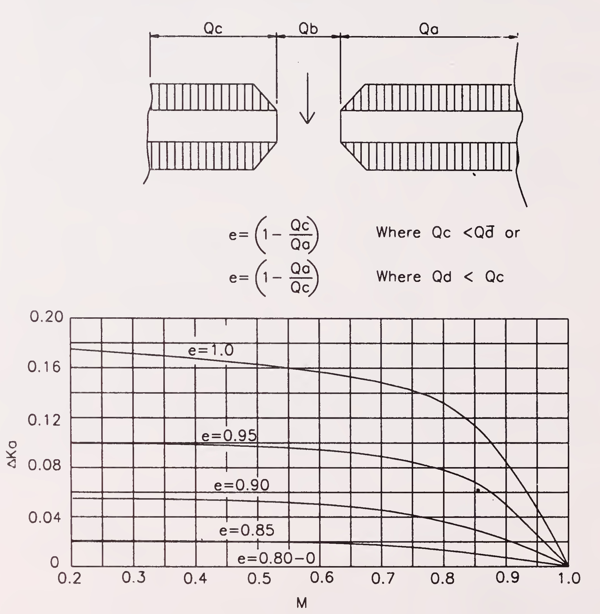
Fig. 5. Incremental backwater coefficient for eccentricity74

(if the cross section is extremely asymmetrical so that Qa < 20 per cent of Qc or vice versa, the afflux coefficient will be some what larger than for comparable value of M shown on the base curve).
The method of computation of incremental backwater coefficient ΔΚ5 for the skewed crossing differs from that of normal crossing in the following respects:
The bridge opening ratio M is computed on the projected length of bridge rather than on the length along the centre-line. The length is obtained by projecting the bridge opening upstream parallel to the general direction of flood flow as shown in Fig.6. The general direction of flow means the direction of flood flow as it existed previous to the placement of the embankments in the stream. The length of the constricted opening is bs cos ϕ and the area An2 is based on this length. The velocity head, V2n2/2g to be substituted in expression (1) is based on the projected area An2. Fig. 7 may be used for determining the incremental backwater coefficient (ΔΚ5) for the effect of skew, for wing walls and spill-through type abutments. It varies with opening ratio M, the angle of skew of the bridge ϕ, with the general direction of flood flow and the alignment of the abutment faces as indicated by the sketches in Fig. 7.

A weighted average value of the kinetic energy is obtained by multiplying the average velocity head computed as (Q/A1)2/ 2g by a kinetic energy coefficient α1 defined as
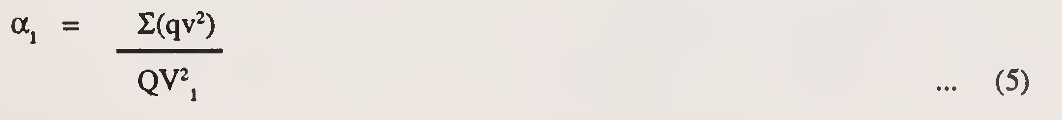
A second coefficient α2 is required to correct the velocity head for non-uniform velocity distribution under the bridge.75
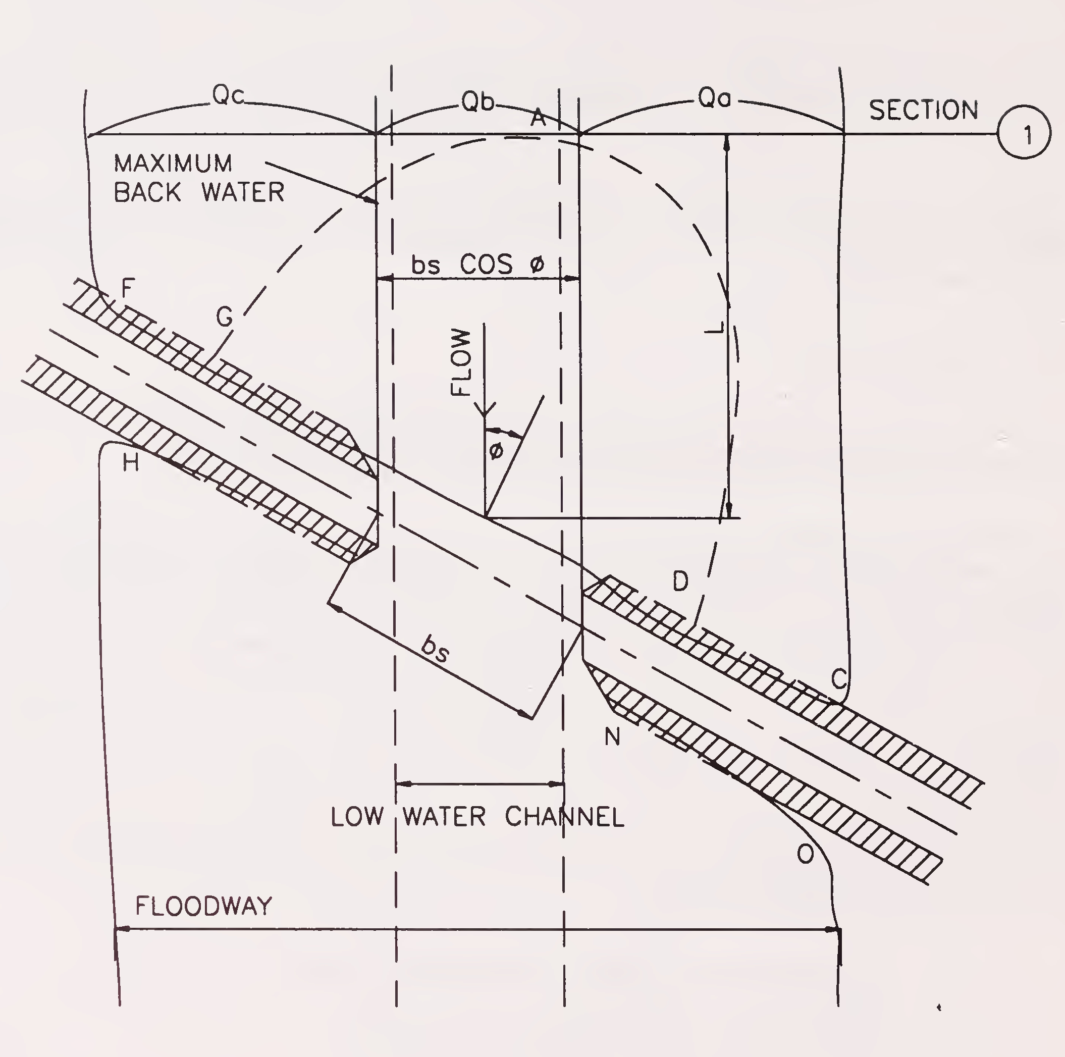
Fig. 6. Skewed crossings

The value of α1 can be computed but α2 is not readily available, knowing the value of 1 and opening ratio M, use Fig. 8 for estimating α2.76
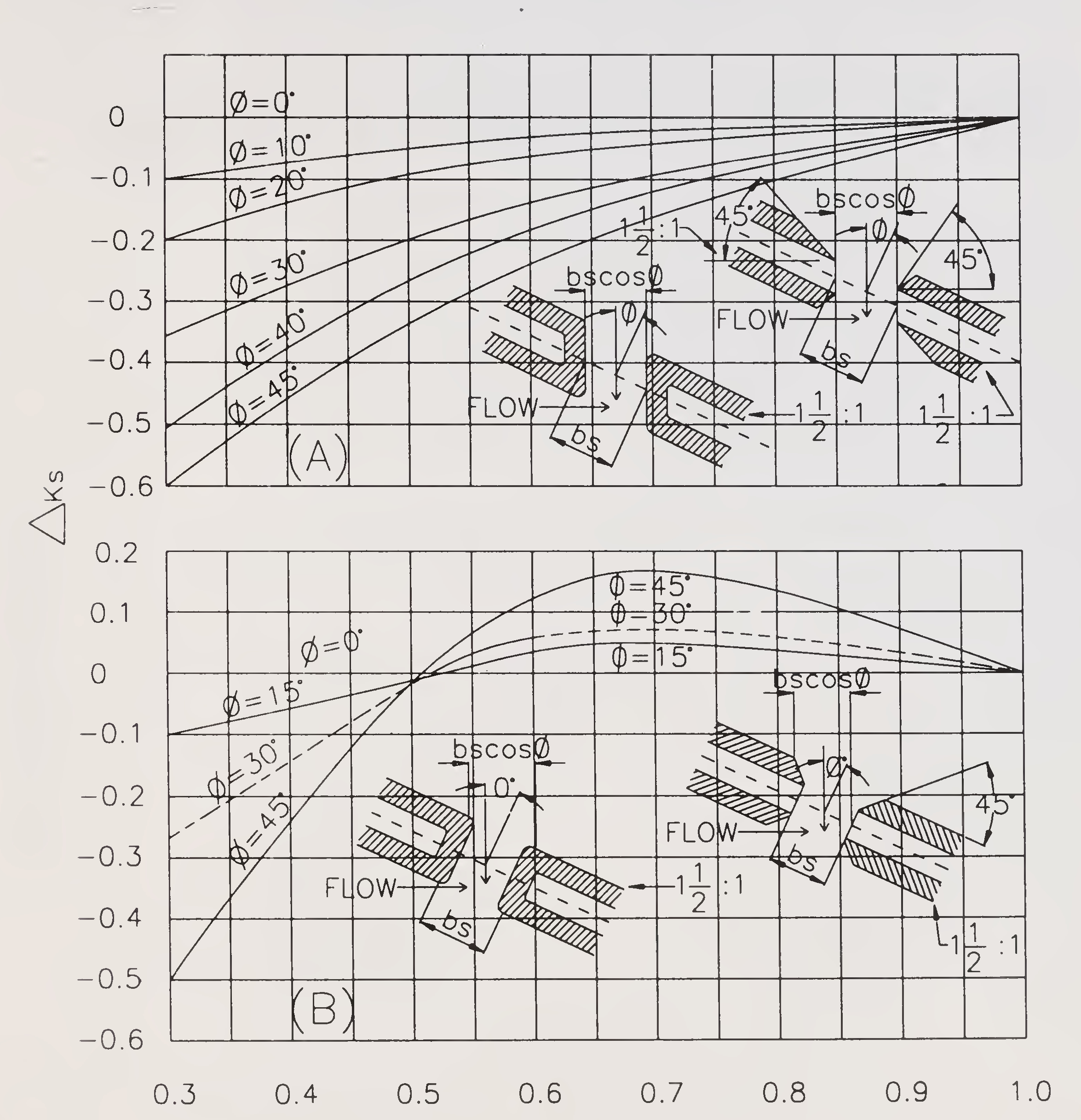
Fig. 7. Incremental backwater coefficient for skew77
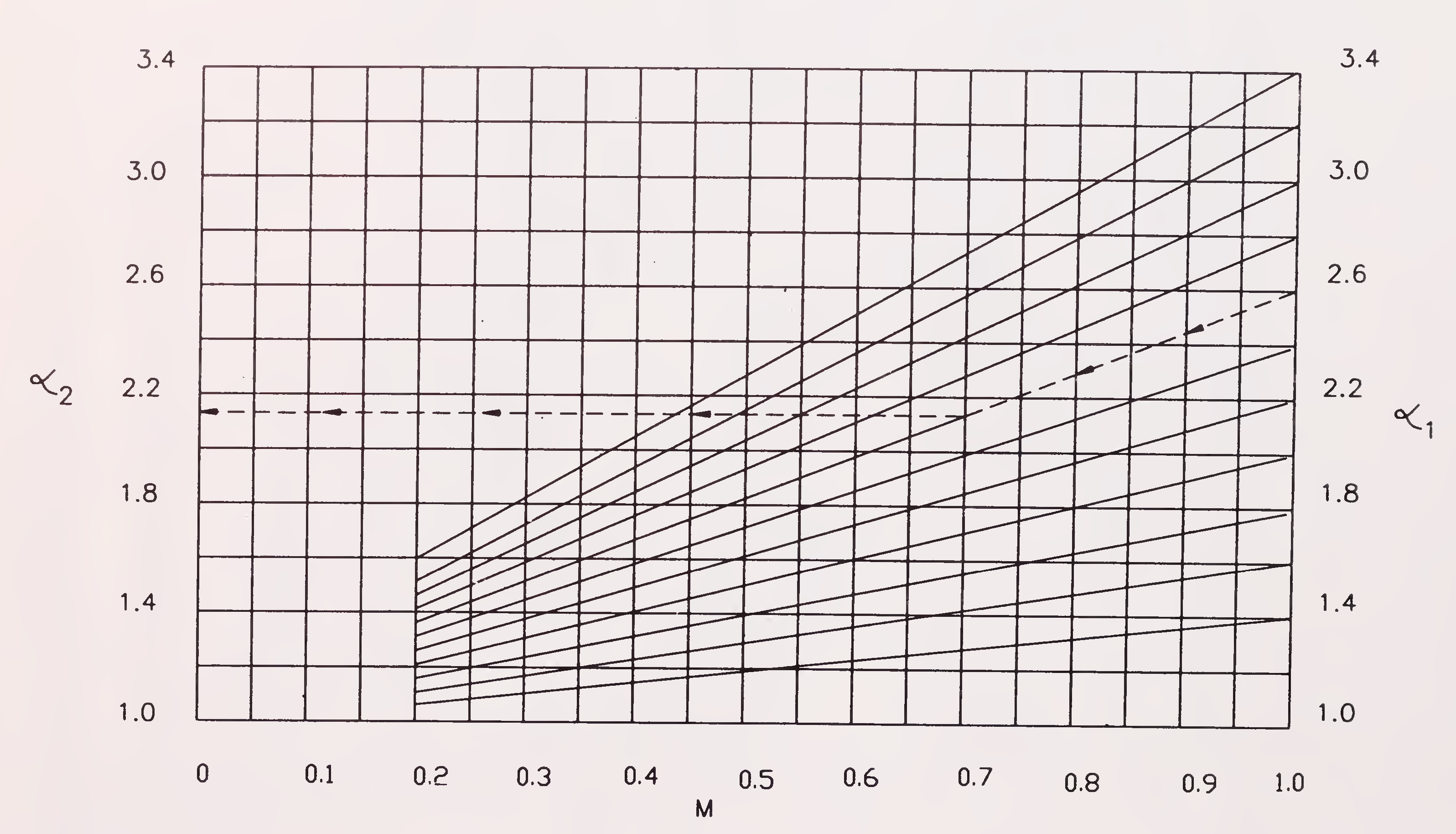
Fig. 8. Aid for estimating 278
5. Having known the value of K*, α2 and Vn the approximate value of h*1 using the first part of the expression (1) is first determined. The value of A1 in the second part of the expression (1) which depends on h*1 can then be determined and the second term of expression (1) is evaluated and total backwater or afflux h*1 (in ft) found.
Note: The extract given in this Appendix has been taken from the Book “Hydraulics of Bridge Waterways” with the permission of U.S. Deptt. of Transportation (Federal Highway Administration).79
Appendix 1 (b)
(Contd.)
(Para 4.6.3)
NOTATIONS
| Symbol | Definition | Reference to Fig. | |
|---|---|---|---|
| A1 | = | Area of flow including backwater in section 1 (sq.ft.) | 1(B) and 2(B) |
| An1 | = | Area of flow below normal water surface in section 1 (sq.ft.) | 1(B) and 2(B) |
| A2 | = | Area of flow including backwater in section 2 (sq.ft.) | 1(C) and 2(C) |
| An2 | = | Gross area of flow in constriction below normal water surface at section 2(sq.ft.) | 1(C) and 2(C) |
| A4 | = | Area of flow at section 4 at which normal water surface is re-established (sq.ft.) | 1(A) and 2(A) |
| Ap | = | Projected area of piers normal to flow, between normal water surface and stream bed) (sq.ft.) | 4 |
| b | = | Width of constriction (ft.) | 1(C) and 2(C) |
| bs | = | Width of constriction of a skew crossing measured along centre line of roadway (ft.) | 6 |
| e | = | 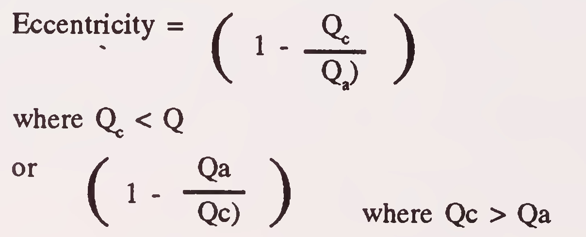
| |
| g | = | Acceleration due to gravity = 32.2 ft./sec2 | |
| h1* | = | Total backwater (afflux) or rise above normal stage at section 1 (ft) | 1(A) and 2(A) |
| J | = |
|
4 |
| Kb | = | Backwater coefficient from base curve | 3 |
| ∆Kp | = | Incremental backwater coefficient for piers | 480 |
| ΔΚe | = | Incremental backwater coefficient for eccentricity | 5 |
|
ΔΚs | = | Incremental backwater coefficient for skew | 7 |
| K* | = | Kb+∆Kp+∆Ke+∆Ks | |
| Total backwater coefficient for sub-critical flow | |||
| M | = | Bridge opening ratio 
|
|
| Qb | = | Flow in portion of the channel within projected length of bridge at section 1 (cusecs) | 1 and 2 |
| QaQc | = | Flow over that portion of the natural flood plain obstructed by the roadway embankment (cusecs) | 1 and 2 |
| Q | = | Qa + Qb + Qc = Total discharge (cusecs) | |
| q | = | Discharge in sub-section (cusecs) | |
| v2 | = |  Average velocity at Section-1 (ft/sec.) Average velocity at Section-1 (ft/sec.) |
|
| v2 |  Average velocity in constriction at section 2 (ft/sec.) Average velocity in constriction at section 2 (ft/sec.) |
||
| Vn2 | = |  Average velocity in constriction for flow at normal stage (ft/sec.) Average velocity in constriction for flow at normal stage (ft/sec.) |
|
| V | = | Average velocity in a sub-section (ft/sec) | |
|
1 | = | Velocity head coeffcient at Section 1 | |
| 2 | = | Velocity head coefficient for constriction | 8 |
| σ | = | Multiplication factor for influence of M on incremental backwater coefficient for piers | 4(B) |
| ϕ | = | Angle of skew (degrees) | 681 |
Appendix 2
(Para 5.3.7.3)
For laying of wire crates in aprons of bridges, two situations arise.
Wire crates shall be made from hot dip galvanised mild steel wire of dia, not less than 4 mm in annealed condition having tensile strength of 300-450 MPa conforming to IS: 280-1978 (soft). The galvanised coating shall be heavy coating for soft condition conforming to IS: 4826 - 1979. The mesh of crate shall not be more than 150 mm. Wire crates for shallow accessible situations shall be 3m × 1.5 m × 1.25 m in size. Where these have to be deposited and there is a chance of overturning, the crate shall be divided into 1.5 m compartments by cross netting.
For deep or inaccessible situations, wire crates can be made smaller subject to approval of the Engineer-in-Charge.
Wire crates built in-situ, shall neither be larger than 7.5 m × 3.0 m × 0.6 m nor smaller than 2 m × 1 m × 0.3 m. Sides of large crates shall be securely stayed at intervals not exceeding 1.5 m to prevent bulging.
The netting shall be made by fixing a row of spikes on a beam at a spacing equal to the mesh. The beam must be a little longer than the width of netting required. The wire is to be cut to lengths about three times the length of the net required. Each piece is bent at the middle around one of the spikes and the weaving commenced from one comer.
A double twist shall be given at each inter-section. This twisting shall be carefully done by means of a strong iron bar, five and half turns being given to the bar at each splice.
The bottom and two ends of the crate or mattress shall be made at one time. The other two sides shall be made separately and shall be secured to the bottom and the ends by twisting adjacent wires together. The top shall be made separately and shall be fixed in the same manner as the sides alter the crate or mattress has been filled.
Wherever possible, crates shall be placed in position before filling with boulders. The crates shall be filled by carefully hand packing the boulders as tightly as possible and not by merely throwing in stones or boulders.82
Appendix 3
(Para 11.2.4)
MATHEMATICAL MODEL STUDIES
The alluvial rivers are regulatory in the sense that they adjust their characteristics in response to any change in the environment. These environmental changes may occur naturally or may be result of such human activities as river training, diversion, construction of dams, channelisation, bank protection, constriction of bridges, sand and gravel mining etc. Such changes distort the natural equilibrium of a river. The river will adjust to the new conditions by changing its slope, roughness, cross sectional shape or meandering pattern. Within the existing constraints, any one or combination of these characteristics may adjust as the river seeks to maintain the balance between its ability to transport the sediment and the sediment load imposed.
River channel behaviour often needs to be studied in its natural state and its responses to the afore mentioned human activities. Studies of river hydraulics, sediment transport and river channel changes may be through physical modelling or mathematical modelling or both. Physical modelling has been relied upon traditionally to obtain the essential design information. What limits the accuracy of physical model is the scale distortion which is almost unavoidable particularly when it involves sedimentation. Mathematical modelling of erodible channels has been advanced with progress in physics of fluvial processes and computer techniques. Since the actual size river is applied in mathematical modelling, there is no scale distortion. The applicability and accuracy of model depends on the physical foundation and numerical techniques employed.
Mathematical model of river channel changes require adequate and sufficient physical relationships for the fluvial processes. Although the processes are governed by the principles of continuity, flow resistance, sediment transport and bank stability, such relations are insufficient to explain the time and spatial variations of channel geometry in an alluvial river. Generally width adjustment occurs concurrently with changes in the river bed profile, slope, channel pattern, roughness and so on. These changes are closely inter related and delicately adjust to establish or to maintain the dynamic state of equilibrium. While any factor imposed upon the river is usually absorbed by the combination of the above responses, the extent of each type of resistances is inversely related to the resistance to change. For example, in response to deficit in sediment supply, the slope of the river is generally reduced more through meander development than through degradation because the latter is usually inhibited by the coarsening of the bed material. Also, there tends to be more adjustment in width in erodible bank materials than in erosion resistant bank materials.83
The following are some of the cases where man made changes affect the dynamic equilibrium of the river:
Water routing provides temporal and spatial variations of the stage, discharge, energy gradient and other hydraulic parameters in the channel. The water routing component has the following major features:
The continuity and momentum equations in the longitudinal direction are derived as follows:
 84
84

| Where | Q | = | discharge |
| A | = | cross sectional area of flow | |
| t | = | time | |
| X | = | longitudinal direction along the discharge centre line measured from the upstream entrance | |
| q | = | lateral inflow rate per unit length | |
| H | = | stage of water surface elevation | |
| S | = | energy gradient | |
| g | = | acceleration due to gravity |
The upstream boundary condition for water routing is the inflow hydrograph and the downstream condition is the stage discharge relation.
The longitudinal energy gradient can be evaluated using any valid flow resistance relationship. If Manning’s formula is employed, the roughness coefficient ‘n’ must be selected according to the bed diameter and river conditions.
The sediment routing component has following major features:
These features are evaluated at each time step and results so obtained are used in determining the changes in channel configuration. To treat at the time dependent and non equilibrium sediment transport the bed material at each section is divided into several size fractions and sediment transport is computed using suitable formula.
The equation of continuity for sediment in the longitudinal direction is given by:

| Where | λ | = | porosity of the bed material |
| Qs | = | bed material discharge | |
| qs | = | lateral inflow rate of sediment per unit length85 |
According to this equation, the time change of cross sectional area is related to the longitudinal gradient in sediment discharge and lateral sediment inflow. In the absence of lateral sediment inflow, longitudinal imbalance in Qs is absorbed by channel adjustments towards establishing uniformity in Qs.
The change in cross sectional area for each section at each time step is obtained through numerical solution of Equation 3. This area change will be applied to the bed and banks following correction techniques for channel width and channel bed profile.
One dimensional mathematical models like water routing and backwater models to solve problems such as dam break, flood wave transmission, effect of bridge constriction etc. were commonly in use before the introduction of computers. Now with the easy access to mainframe computer and personal computers with large memories, it has become possible to develop software and study the morphological changes of short and long duration by simulation models. Institutes such as Central Water Commission, Central Water and Power Research Station, Pune, National Institute of Hydrology, Roorkee, and some of the State Irrigation Research Institutes and Indian Institute of Technology at Delhi, Bombay etc. have developed suitable softwares to study these aspects in the area of river engineering.86
Appendix 4
(Para 11.5.1)
MODEL LIMITATIONS
In the mobile bed river model, the results lack scalar transformation to prototype. They cannot be applied quantitatively, however, they can be considered as qualitative. Some of these are:
Silting in model is much slower than in the prototype while the scouring takes place during the early stages of the hydrograph in model. Firstly, this suggested scour hole is due to dissimilar horizontal and vertical scales, scour holes tend to be proportional to vertical scale while the width tends to be proportional to horizontal scale. Secondly, in falling stages of the hydrograph bed movement in model is negligible, as such the scour hole which used to be filled up in prototype does not fill up in model. However, the scour depth obtained gives an idea of the formation and direction of new channels and is helpful for design of launching apron.
In prototype, most of the sediment moves in suspension and very little as bed load. Silting is mostly due to suspended sediment, while in model, bed load is much higher than the suspended. Moreover, due to limited length and duration of run of model the suspended sediment does not settle down. The silting is only indicated by the slack flow or return flow of low intensities.
Throw off in distorted model is different from the corresponding throw off in the prototype. This is partly due to the increased height in comparison to width of the structure, and partly due to very steep side slopes. Some of the research institutes have constructed full width as well as part width river models to reproduce approximately similar effects. First full width river model is constructed to small scales, the entry conditions in part width model are adjusted to reproduce the lines of flow observed from full width model. The throw off in part width model obtained is reproduced in full width model. The process is repeated till approximate similarity is obtained.
Due to uncertainty of uniform bed movement, further development of meanders in case of meandering rivers, is not correctly reproduced in the distorted models, It is due to this reason that correct development of new channels, resurvival of old channels and further silting of islands is seldom depicted from these models.87
In vertically exaggerated models for bridges and barrages the thickness of the piers is much less and the width to depth ratio of model span and prototype span is not same. As such sometimes either number of piers are reduced to maintain the above ratio, or a few piers are combined to form one pier, the shape of such piers differs from that in prototype and effects the coefficient due to changed shape.
To reproduce correct silting in model, the hydrograph in the model should be run for a longer time. This time is defined as hydraulic time and the time scale for hydraulic time is:
(T1)r = Lr hr(-05)
When the sediment movement is guided by tractive force and the sedimenting time scale could be obtained by tractive force method, this works out to (T2)r = hr1.5. The only solution to this is that hr should be equal to Lr0.5 which results in higher exaggerations so more departure from prototype. Generally, time scale adopted is hydraulic time. In the above formulae (T1)r and (T2)r are the time scales, Lr is the length scale and hr is the height scale of the model.88
 = Ratio due to area obstructed by piers to gross area of bridge waterway below normal water surface at section 2