This library of books, audio, video, and other materials from and about India is curated and maintained by Public Resource. The purpose of this library is to assist the students and the lifelong learners of India in their pursuit of an education so that they may better their status and their opportunities and to secure for themselves and for others justice, social, economic and political.
This item has been posted for non-commercial purposes and facilitates fair dealing usage of academic and research materials for private use including research, for criticism and review of the work or of other works and reproduction by teachers and students in the course of instruction. Many of these materials are either unavailable or inaccessible in libraries in India, especially in some of the poorer states and this collection seeks to fill a major gap that exists in access to knowledge.
For other collections we curate and more information, please visit the Bharat Ek Khoj page. Jai Gyan!
IRC : 73-1980
Published by
THE INDIAN ROADS CONGRESS
Jamnagar House, Shahjahan Road,
New Delhi-110011
1990
Price Rs. 120/-
(Plus Packing & Postage)
MEMBERS OF THE SPECIFICATIONS & STANDARDS COMMITTEE
| 1. | J.S. Marya (Chairman) |
Director General (Road Development) & Addl. Secy, to the Govt. of India, Ministry of Shipping & Transport |
| 2. | R.P. Sikka (Member-Secretary) |
Chief Engineer (Roads), Ministry of Shipping & Transport |
| 3. | Qazi Mohd. Afzal | Development Commissioner, Jammu & Kashmir |
| 4. | R.C. Arora | N.D S.E. Part I, New Delhi |
| 5. | R.T. Atre | Secretary to the Govt. of Maharashtra, PW & H Deptt. |
| 6. | M.K. Chatterjee | Chief Executive Officer, West Bengal Industrial Infrastructure Development Corpn. |
| 7. | E.C. Chandrasekharan | Chief Engineer, Pamban Bridge Project Madras |
| 8. | M.G. Dandavate | Engineer, Concrete Association of India |
| 9. | J. Datt | Chief Engineer (Retd.), Greater Kailash, New Delhi-110048 |
| 10. | Dr. M.P. Dhir | Deputy Director & Head, Roads Division, Central Road Research Institute |
| 11. | Dr. R.K. Ghosh | Deputy Director & Head, Rigid and Semi Rigid Pavements Division, Central Road Research Institute |
| 12. | B.R. Govind | Director of Designs, Engineer-in-Chief’s Branch, AHQ |
| 13. | I.C. Gupta | Engineer-in-Chief, Haryana P.W.D., B & R |
| 14. | S.A. Hoda | Project Manager-cum-Managing Director, Bihar State Bridge Construction Corporation Ltd. |
| 15. | M.B. Jayawant | Synthetic Asphalts, 24, Carter Road, Bombay-400050 |
| 16. | D.R. Kohli | Manager, Electronics Data Processing, Bharat Petroleum Corporation Ltd. |
| 17. | S.B. Kulkarni | Manager (Asphalt), Indian Oil Corporation Ltd. |
| 18. | F.K. Lauria | Addl. Chief Engineer (N.H.), Rajasthan P.W.D. |
| 19. | H.C. Malhotra | Engineer-in-Chief & Secy. to the Govt., H.P. P.W.D. |
| 20. | M.R. Malya | Development Manager, Gammon India Ltd., Bombay |
| 21. | O. Muthachen | Poomkavil House, P.O. Punalur (Kerala) |
| 22. | K. Sunder Naik | Chief Engineer (Retd.), Indranagar Bangalore |
| 23. | K.K. Nambiar | “Ramanalaya”, 11, First Crescent Park Road, Gandhinagar, Adyar, Maidras-600020 |
| 24. | T.K. Natarajan | Deputy Director & Head, Soil Mechanics Division, Central Road Research Institute |
| 25. | M.D. Patel | Secretary to the Govt. of Gujarat Buildings and Communication Department |
| 26. | Satish Prasad | Manager, Indian Oil Corporation |
| 27. | S.K. Samaddar | Chief Project Administrator, Hooghly River Bridge Commissioners, Calcutta |
| 28. | Dr. O.S. Sahgal | Principal, Punjab Engineering College, Chandigarh |
| 29. | N. Sen | Chief Engineer (Retd.), 12, Chitranjan Park, New Delhi-110019 |
| 30. | D. Ajitha Simha | Director (Civil Engineering), Indian Standards Institution |
| 31. | Maj. Genl. J.S. Soin | Director General Border Roads |
| 32. | Dr. N.S. Srinivasan | Chief Executive, National Traffic Planning & Automation Centre |
| 33. | Dr. Bh. Subbaraju | Sri Ramapuram, Bhimavaram-534202 (A.P.) |
| 34. | Prof. C.G. Swaminathan | Director, Central Road Research Institute |
| 35. | Miss P.K. Thressia | Chief Engineer (Construction), Kerala |
| 36. | The Director (Prof. G.M. Andavan) |
Highways Research Station, Madras |
GEOMETRIC DESIGN STANDARDS FOR RURAL (NON-URBAN) HIGHWAYS
“Geometric design” deals with the visible elements of a highway. Sound geometric design results in economical operation of vehicles and ensures safety.
The Specifications and Standards Committee of the Indian Roads Congress had previously published a few Papers on geometric aspects of design. The first Paper entitled: “Horizontal and Transition Curves for Highways” appeared in the I.R.C. Journal in 1947. This was followed by two other Papers on “Sight Distance and Vertical Curves” in 1950 and 1952 respectively. For many years, these Papers served as a guide for design of highways in this country. Later, in 1966, some important extracts from these Papers were published by the Congress under the title “Geometries of Roads”.
Following the adoption of metric system, there was a need to revise this publication with suitable modifications in the light of other standards brought out by the I.R.C. in the intervening period as also more recent practices round the world. To fulfil this need, a new draft was prepared in the I.R.C. Secretariat by L.R. Kadiyali and A.K. Bhattacharya. This was reviewed and modified by a Working Group set up by the Specifications and Standards Committee consisting of:
Dr. M.P. Dhir
R.P. Sikka
A.K. Bhattacharya
The modified draft was approved by the Specifications and Standards Committee in their meeting held on 16th May, 1977. It was later approved by the Executive Committee through circulation and then by the Council of the Indian Roads Congress in their 93rd meeting held on the 3rd June, 1978 subject to certain modifications which were left to a Working Group comprising Prof. C.G. Swaminathan, R.C. Singh, Col. Avtar Singh, R.P. Sikka and P.C. Bhasin, Secretary IRC. The final modification and editing of the1
text was done jointly by R.P.Sikka, Member-Secretary, Specifications and Standards Committee and K. Arunachalam.
The publication is based primarily on.existing standards and recommendations of the Indian Roads Congress, with suitable modifications and additions in the light of current engineering practice. The standards prescribed are essentially advisory in nature but may be relaxed somewhat in very difficult situations if considered judicious. Effort in general should, however, be to aim at standards higher than the minimum indicated.
The text deals with geometric design standards for rural highways**, i.e. non-urban roads located predominantly in open country outside the built-up area. The alignment may however pass through isolated stretches of built-up nature as long as character of the road as a whole does not change. The standard is not applicable to urban roads or city streets. It is also not applicable to expressways. Geometric design elements of road intersections are not considered in the standard either.
The geometric features of a highway except crosssectional elements do not lend to stage construction. Geometric defitciencies are costly and sometimes impossible to rectify later on due to the subsequent roadside development. Therefore, it is essential that geometric requirements should be kept in view right in the beginning.
Non-urban roads in India are classified into five categories:
**These should not be confused with Rural Roads which refer commonly to Other District Roads and Village Roads. While geometric design elements of Rural Roads are duly covered in this publication alongwith roads of higher category, more comprehensive guidance about different facets of design and construction of the Rural Roads can be had from the IRC Special Publication No. 20, “Manual on Route Location, Design, Construction and Maintenance of Rural Roads (Other District Roads and Village Roads)".
2National Highways are main highways running through the length and breadth of the country connecting major ports, foreign highways, State capitals, large industrial and tourist centres etc.
State Highways are arterial routes of a State linking district headquarters and important cities within the State and connecting them with National Highways or highways of the neighbouring States.
Major District Roads are important roads within a district serving areas of production and markets, and connecting these with each other or with the main highways.
Other District Roads are roads serving rural areas of production and providing them with outlet to market centres, taluka/ tehsil headquarters, block development headquarters, or other main
roads.
Village Roads are roads connecting villages or groups of villages with each other and to the nearest road of a higher category.
The geometric design of a highway is influenced significantly by terrain conditions. Economy dictates choice of different standards for different types of terrain. Terrain is classified by the general slope of the country across the highway alignment, for which the criteria given in Table 1 should be followed. While classifying a terrain, short isolated stretches of varying terrain should not be taken into consideration.
| S. No. | Terrain classification | Per cent cross slope of the country |
|---|---|---|
| 1. | Plain | 0-10 |
| 2. | Rolling | 10-25 |
| 3. | Mountainous | 25—60 |
| 4. | Steep | Greater than 60 |
5.1. Choice of design speed depends on the function of the road as also terrain conditions. It is the basic parameter which determines all other geometric design features. Design speeds for various classes of roads should be as given in Table 2.3
| s. No. | Road classification | Design speed, km/h | |||||||
|---|---|---|---|---|---|---|---|---|---|
| Plain terrain | Rolling terrain | Mountainous terrain | Steep terrain | ||||||
| Ruling design speed | Minimum design speed | Ruling design speed | Minimum design speed | Ruling design speed | Minimum design speed | Ruling design speed | Minimum design speed | ||
| 1. | National and State Highways | 100 | 80 | 80 | 65 | 50 | 40 | 40 | 30 |
| 2. | Major District Roads | 80 | 65 | 65 | 50 | 40 | 30 | 30 | 20 |
| 3. | Other District Roads | 65 | 50 | 50 | 40 | 30 | 25 | 25 | 20 |
| 4. | Village Roads | 50 | 40 | 40 | 35 | 25 | 20 | 25 | 204 |
Normally “ruling design speed” should be the guiding criterion for correlating the various geometric design features. “Minimum design speed” may, however, be adopted in sections where site conditions, including costs, do not permit a design based on the “ruling design speed”.
The design speed should preferably be uniform along a given highway. But variations in terrain may make changes in speed unavoidable. Where this is so, it is desirable that the design speed should not be changed abruptly, but in a gradual manner by introducing successive sections of increasing/decreasing design speed so that the road users get conditioned to the change by degrees.
Road land width (also termed the right-of-way) is the land acquired for road purposes. Desirable land width for different classes of roads is indicated in Table 3.
| S.No. | Road classification | Plain and rolling terrain | Mountainous and steep terrain | ||||
|---|---|---|---|---|---|---|---|
| Open areas | Built-up areas | Open areas | Built-up areas | ||||
| Normal | Range | Normal | Range | Normal | Normal | ||
| 1. | National and State Highways | 45 | 30-60 | 30 | 30-60 | 24 | 20 |
| 2. | Major District Roads | 25 | 25-30 | 20 | 15-25 | 18 | 15 |
| 3. | Other District Roads | 15 | 15-25 | 15 | 15-20 | 15 | 12 |
| 4. | Village Roads | 12 | 12-18 | 10 | 10-15 | 9 | 9 |
In high banks or deep cuts, the land width should be suitably increased. Similarly, a higher value should be adopted in unstable or landslide-prone areas. The need for a wider right-of-way at important road intersections should also be kept in view.5
If a road is expected to be upgraded to a higher classification in the foreseeable future, the land width should correspond to the latter.
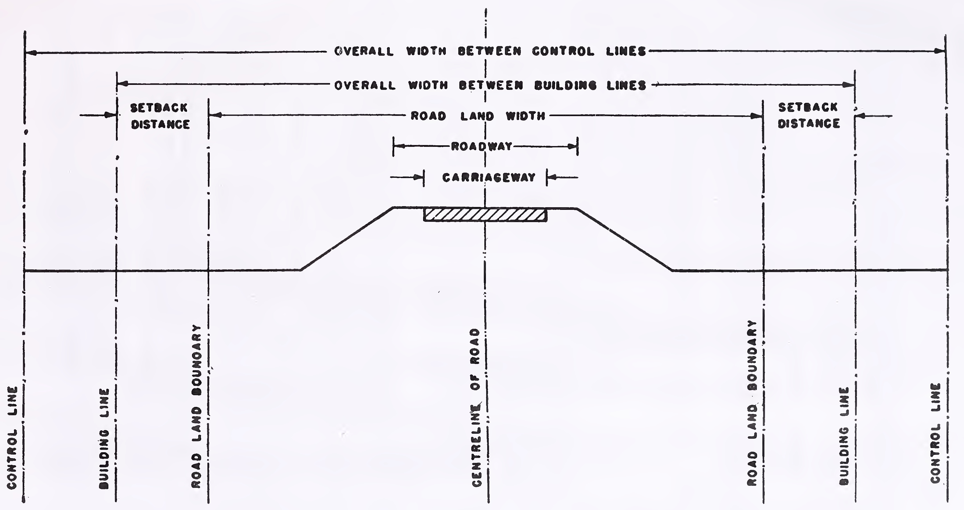
In order to prevent overcrowding and preserve sufficient space for future road improvement, it is advisable to lay down restrictions on building activity along the roads. Building activity should not be allowed within a prescribed distance from the road, which is defined by a hypothetical line set back from the road boundary and called the “Building Line”. In addition, it will be desirable to exercise control on the nature of building activity for a further distance beyond the building line upto what are known as the “Control Lines”. Building and control lines are illustrated in Fig. 1 with respect to the road centre line and road boundary.
Recommended standards for building and control lines are given in Table 4. For more details about measures for preventing
| Road classification | Plain and rolling terrain | Mountainous and steep terrain | |||
|---|---|---|---|---|---|
| Open areas | Built-up areas | Open areas | Built-up areas | ||
| Overall width between Building Lines (metres) |
Overall width between Control Lines (metres) |
Distance between Building Line and road boundary (set-back) (metres) |
Distance between Building Line and road boundary (set-back) (metres) |
||
| 1 | 2 | 3 | 4 | 5 | 6 |
| 1. National and State Highways | 80 | 150 | 3-6 | 3-5 | 3-5 |
| 2. Major District Roads | 50 | 100 | 3-5 | 3-5 | 3-5 |
| 3. Other District Roads | 25/30* | 35 | 3-5 | 3-5 | 3-5 |
| 4. Village Roads | 25 | 30 | 3-5 | 3-5 | 3-5 |
Notes : 1. *If the land width is equal to the width between building lines indicated in this column, the building lines should be set-back 2.5 m from the road land boundary.
2. See Fig. 1 for position of building lines, control lines and setback distance relative to the road centre line and road land boundary.6
Fig. 1. Road land boundary, building lines and control lines7
ribbon. development along roads, reference may be made to IRC Special Publication No. 15, “Ribbon Development along Highways and its Prevention’’, also IRC : 62-1976 “Guidelines for Control of Access on Highways”.
The width of roadway for single and two-lane roads in plain and rolling terrain should be as given in Table 5.
| S. No. | Road classification | Roadway width (metres) |
|---|---|---|
| 1. | National Highways and State Highways
(single or two lanes) |
12.0 |
| 2. | Major District Roads
(single or two lanes) |
9.0 |
| 3. | Other District Roads | |
| (i) single lane | 7.5 | |
| (ii) two lanes | 9.0 | |
| 4. | Village Roads
(single lane) |
7.5 |
| Note: In case of State Highways having single-lane pavement, the width of roadway might be reduced to 9 m if the possibility of widening the carriageway to two lanes is considered remote. | ||
The width of roadway, exclusive of side drains and parapets, for single and two-lane roads in mountainous and steep terrain should be as indicated in Table 6. In certain cases, passing places may be required in addition, see para 6.2.3.
Passing places or lay-byes should be provided on single lane roads in mountainous and steep terrain to cater to the following requirements:
| S. No. | Road classification | Roadway width (metres) |
|---|---|---|
| 1. | National Highways and State Highways | |
| (i) single lane | 6.25 | |
| (ii) two lanes | 8.8 | |
| 2. | Major District Roads and Other District Roads (single lane) | 4.75 |
| 3. | Village Roads (single lane) | 4.0 |
Notes:
| ||
Passing places are not necessary on two-lane National and State Highways having roadway width in accordance with Table 6. But on single lane sections having narrower roadway, it may be desirable to provide some passing places depending on actual needs. On other roads, these should be provided in general at the rate of 2-3 per kilometre. Their exact location should be judiciously determined taking into consideration the available extra width on curves and visibility.
Normally the passing places/lay-byes should be 3.75 m wide, 30 m long on the inside edge (i.e. towards the carriageway side), and 20 m long on the farther side.9
For nuilti-lane highways, roadway width should be adequate for the requisite number of traffic lanes, besides shoulders and central median. Width of shoulders should in general be 2.5 metres. For width of carriageway and median, reference may be made to paras 6.4 and 6.6 respectively.
Cross-drainage structures are difficult to widen at a later stage. As such, the roadway width for them should be decided very carefully at the planning stage itself. The minimum recommended values in this regard are given in paras 6.3.2 and 6.3.3. For roads being built to lower standards initially for some reason, or those which are expected to be upgraded/ widened in.the foreseeable future, it will be desirable to go in for a higher roadway width at the cross-drainage structures right in the beginning.
In plain and rolling terrain, the overall width on culverts (measured from outside to outside of the parapet walls) should equal the normal roadway width given in Table 5. In mountainous or steep terrain, the clear roadway width available on the culverts (measured from inside to inside of parapet walls or kerbs) should be as below:
| All roads other than Village Roads | ... | As given in Table 6 |
| Village Roads | ||
| minimum | ... | As given in Table 6 |
| desirable | ... | 4.25 m |
Bridges (grater than 6m span): At bridges, the clear width of roadway between kerbs should be as under:
| Single-lane bridge | ... | 4.25 m |
| Two-lane bridge | ... | 7.5 m |
| Multi-lane bridge | ... | 3.5 m per lane plus 0.5 m for each carriageway |
At causeways and submersible bridges, the minimum width of roadway (between kerbs) should be 7.5 m, unless the width is specially reduced by the competent authority.
Where a footpath is provided for the use of pedestrians, its width should not be less than 1.5 m.10
The standard width of carriageway shall be as indicated in Table 7. The total width should be determined in relation to the design traffic and capacity of the roadway, see Section 7.
| Width of carriageway (metres) | |||
|---|---|---|---|
| Single lane | Two lanes without raised kerbs | Two lanes with raised kerbs | Multi-lane pavements, width per lane |
| 3.75** | 7.0 | 7.5 | 3.5 |
Notes:
| |||
Where the carriageway width changes, e.g. from single lane to two lanes or two lanes to four lanes, the transition should be effected through a taper of 1 in 15 to 1 in 20.
The width of shoulders for each class of highway can be directly obtained using Tables 5, 6 and 7. Shoulder width will be one-half the difference between the roadway width (Table 5 or 6) and carriageway width (Table 7).
6.6.1. Medians should be as wide as possible, but their width is often restricted by economic considerations. Minimum desirable width of medians on rural highways is 5 metres, but this could be reduced to 3 metres where land is restricted. On long bridges and viaducts, the width of median may be reduced to 1.5 meters, but in any case this should not be less than 1.2 m.
As far as possible, the median should be of uniform width in a particular section of the highway. However, where changes are unavoidable, a transition of 1 in 15 to 1 in 20 must be provided.11
In rolling and hilly country, the median width will be dictated by topography and the individual carriageways could be at different levels.
The camber or crossfall on straight sections of roads should be as recommended in Table 8 for various types of surfaces. For a given surface type, the steeper values in the Table may be adopted in areas having high intensity of rainfall and the lower values where the intensity of rainfall is low.
| S.No. | Surface type | Camber/Crossfall |
|---|---|---|
| 1. | High type bituminous surfacing or cement concrete | 1.7-2.0 per cent (1 in 60 to 1 in 50) |
| 2. | Thin bituminous surfacing | 2.0-2.5 per cent (1 in 50 to 1 in 40) |
| 3. | Water bound macadam, gravel | 2.5-3.0 per cent (1 in 40 to 1 in 33) |
| 4. | Earth | 3.0-4.0 per cent (1 in 33 to 1 in 25) |
Generally, undivided roads on straights should be provided with a crown in the middle and surface on either side sloping towards the edge. However on hill roads this may not be possible in every situation, particularly in reaches with a winding alignment where straight sections are few and far between. In such cases, discretion may be exercised and instead of normal camber the carriageway may be given a uni-directional crossfall towards the hill side having regard to factors such as the direction of superelevation at the flanking horizontal curves, ease of drainage, problem of erosion of the down-hill face etc.
On divided roads, i.e. dual carriageways having a median, it is usual to have a uni-directional crossfall for each carriageway sloping towards the outer edge.
The crossfall for earth shoulders should be at least 0.5 per cent steeper than the slope of the pavement subject to a. minimum of 3 per cent.12
If the shoulders are paved, a crossfall appropriate to the type of surface should be selected with reference to Table 8.
On superelevated sections, the shoulders should normally have the same crossfall as the pavement.
The width of carriageway should be sufficient for the design traffic, i.e. traffic expected on the road in the design year. Design traffic will depend on the rate of growth of traffic, th'e design period, importance of road in the system, nature of roadside development etc. For making capacity computations under mixed traffic conditions, the different types of vehicles should be converted to a common unit known as‘passenger car unit’by multiplying their number with relevant equivalency factors. Tentative values Of equivalency factors are given in Table 9. These are meant for use in open sections in plain terrain away from intersections. For more details in this respect, reference may be made to IRC:64-1976 “Tentative Guidelines on Capacity of Roads in Rural Areas.”
| S.No. | Vehicle type | Equivalency factor |
|---|---|---|
| 1. | Passenger car, tempo, auto-rickshaw, or agricultural tractor | 1.0 |
| 2. | Cycle, motor cycle or scooter | 0.5 |
| 3. | Truck, bus, or agricultural tractor-trailer unit | 3.0 |
| 4. | Cycle rickshaw | 1.5 |
| 5. | Horse-drawn vehicle | 4.0 |
| 6. | Bullock cart** | 8.0 |
| **For smaller bullock-carts, a value of 6 will be appropriate. | ||
For purposes of design, the capacity of different types of roads may be taken as given in Table 10.13
| S. No. | Type of road |
Capacity (Passenger car units per day in both directions) |
|---|---|---|
| 1. | Single-lane roads having a 3.75 m wide carriageway with normal earthen shoulders | 1,000 |
| 2. | Single-lane roads having a 3.75 m wide carriageway with adequately designed hard shoulders 1.0 m wide | 2,500 |
| 3. | Two-lane roads having a 7 m wide carriageway with normal earthen shoulders | 10,000 |
| 4. | Roads of intermediate width, i.e. having a carriageway of 5.5 metres with normal earthen shoulders | 5,000 |
| Note: Capacity of highways having a dual carriageway will depend on factors like the directional split of traffic, degree of access control, composition of traffic etc. Depending on the actual conditions, capacity of a 4-lane divided highway could be upto 20,000-30,000 pcus. | ||
The standards in Table 10 are applicable where the visibility is unrestricted and there are no lateral obstructions within 1.75 m from the edge of pavement. These also presume that only a nominal amount of animal drawn vehicles (say 5-10 per cent) are present in the traffic stream during the peak hour. For more details, reference may be made to IRC:64-1976.
Visibility is an important requirement for the safety of travel on highways. For this, it is necessary that s-ight distance of adequate length should be available in different situations to permit drivers enough time and distance to control their vehicles so that there are no unwarranted accidents.
Three types of sight distance** are relevant insofar as the design of summit vertical curves and visibility at the horizontal curves: Stopping Sight Distance; Overtaking Sight Distance; and Intermediate Sight Distance. Standards for these are given in paras 8.2 to 8.4; and the general principles of their application in para 8.5. Criteria for measurement of the sight distances are set forth in para 8.6. Application of the sight distance requirements at horizontal curves is discussed in para 9.7.
**These are dealt with in greater detail in IRC:66-1976 “Recommended Practice for Sight Distance on Rural Highways”.14
For valley curves, the design is governed by night visibility which is reckoned in terms of the Headlight Sight Distance. This is the distance ahead of the vehicle illuminated by the headlights which is within the view of the driver. Standards for headlight sight distance are given in para 8.7.
Stopping sight distance is the clear distance ahead needed by a driver to bring his vehicle to a stop before meeting a stationary object in his path. Minimum stopping sight distance is given by the sum of: (i) distance travelled during the perception and brake reaction time and (ii) the braking distance. Minimum design values of stopping distance For different vehicle speeds are shown in Table 11. These are based on perception and brake-reaction time of 2.5 seconds and coefficient of longitudinal friction varying from 0.40 at 20 km/h to 0.35 at 100 km/h. For application of Table 11, the speed chosen should be the same as the design speed of the road.
| Speed | Perception and brake reaction | Braking | Safe stopping sight distance (metres) | |||
|---|---|---|---|---|---|---|
| V (km/h) | Time, t (sec.) | Distance (metres) d1=0.278vt | Coefficient of longitudinal friction (f) | Distance (metres)
 |
Calculated values d1+d2 | Rounded off values for design |
| 20 | 2.5 | 14 | 0.40 | 4 | 18 | 20 |
| 25 | 2.5 | 18 | 0.40 | 6 | 24 | 25 |
| 30 | 2.5 | 21 | 0.40 | 9 | 30 | 30 |
| 40 | 2.5 | 28 | 0.38 | 17 | 45 | 45 |
| 50 | 2.5 | 35 | 0.37 | 27 | 62 | 60 |
| 60 | 2.5 | 42 | 0.36 | 39 | 81 | 80 |
| 65 | 2.5 | 45 | 0.36 | 46 | 91 | 90 |
| 80 | 2.5 | 56 | 0.35 | 72 | 118 | 120 |
| 100 | 2.5 | 70 | 0.35 | 112 | 182 | 180 |
Overtaking sight distance is the minimum sight distance that should be available to a driver on a two-way road to enable15
him to overtake another vehicle safely. Optimum condition for design is one in which the overtaking driver can follow the vehicle ahead for a short time while he assesses his chances for overtaking, pulls out his vehicle, overtakes the other vehicle at design speed of the highway, and returns to his own side of the road before meeting any oncoming vehicle from the opposite direction travelling at the same speed.
Design values for overtaking sight distance are given in Table 12. These are based on a time component of 9 to 14 seconds for the actual overtaking manoeuvre depending on design speed, increased by about 2/3rd to take into account the distance travelled by a vehicle from the opposite direction during the same time.
| Speed km/h | Time component, seconds | Safe overtaking sight distance (metres) | ||
|---|---|---|---|---|
| For overtaking manoeuvre | For opposing vehicle | Total | ||
| 40 | 9 | 6 | 15 | 165 |
| . 50 | 10 | 7 | 17 | 235 |
| 60 | 10.8 | 7.2 | 18 | 300 |
| 65 | 11.5 | 7.5 | 19 | 340 |
| 80 | 12.5 | 8.5 | 21 | 470 |
| 100 | 14 | 9 | 23 | 640 |
Intermediate sight distance is defined as twice the safe stopping sight distance. It is the experience that intermediate sight distance affords reasonable opportunities to drivers to overtake with caution.
Design values of intermediate sight distance for different speeds are given in Table 13.16
|
Speed km/h |
Intermediate sight distance (metres) |
|---|---|
| 20 | 40 |
| 25 | 50 |
| 30 | 60 |
| 35 | 80 |
| 40 | 90 |
| 50 | 120 |
| 60 | 160 |
| 65 | 180 |
| 80 | 240 |
| 100 | 360 |
Single/two-lane roads
Normally the attempt should be to provide overtaking sight distance in as much length of the road as possible. Where this is not feasible, intermediate sight distance, which affords reasonable opportunities for overtaking, should be adopted as the next best alternative. In no case however should the visibility correspond to less than the safe stopping distance which is the basic minimum for any road.
No hard and fast rule can be laid down for the application of overtaking sight distance since this will depend on site conditions, economics etc. It will be good. engineering practice however to use overtaking sight distance in the case of following situations:
Divided highways
On divided highways, i.e. dual carriageways having a central median, the design should correspond at least to stopping17
sight distance vide Table 11. It will be desirable, though, for operational convenience and better appearance of the highway' to design for somewhat more liberal values, say upto twice the values given in Table 11.
Undivided four-lane highways
On undivided 4-lane highways there are sufficient opportunities for overtaking within one half of the carriageway, and there should be no need to cross the centre line unless the capacity of the road is grossly deficient. Such roads may, therefore, be designed on the lines of divided highways, i.e. vide para 8.5.3.
Criteria for measuring the different types of sight distance discussed above are given in Table 14.
| S. No. | Sight distance | Driver’s eye height | Height of object |
|---|---|---|---|
| 1. | Safe stopping sight distance | 1.2 m | 0.15 m |
| 2. | Intermediate sight distance | 1.2 m | 1.2 m |
| 3. | Overtaking sight distance | 1.2 m | 1.2 m |
During day time, visibility is not a problem on valley curves. However for night travel the design must ensure that the roadway ahead is illuminated by vehicle headlights to a sufficient length enabling the vehicle to brake to a stop if necessary. This distance, called the headlight sight distance, should at least equal the safe stopping sight distance given in Table 11.
In designing valley curves, the following criteria of measurement should be followed as regards the -headlight sight distance:
Uniformity of design standards is one of the essential .requirements of a road alignment. In a given section, there must be consistent application of a design element to avoid unexpected situations being created for the drivers. For instance, a short sharp curve in an otherwise good alignment is bound to act as an accident-prone spot if the designer is not vigilant. Similarly, any unnecessary break in horizontal alignment at cross-drainage structures should be avoided.
As a general rule, the horizontal alignment should be fluent and blend well with the surrounding topography. A flowing line which conforms to natural contours is aesthetically preferable to one with long tangents slashing through the terrain. This would not only help in limiting the damage to the environment but also assist in preservation of natural slopes and plant growth. Due consideration should also be given to the conservation of existing features. This aspect is dealt with at length in IRC Special Publication No. 21-1979 “Manual on Landscaping of Roads”.
Long tangent sections exceeding 3 km in length should be avoided as far as possible. A curvilinear alignment with long curves is better from the point of safety and aesthetics.-
As a normal rule, sharp curves should not be introduced at the end of long tangents since these can be extremely hazardous.
Short curves give appearance of kinks, particularly for small deflection angles, and should be avoided. The curves should be sufficiently long and have suitable transitions to provide pleasing appearance. Curve length should be at least 150 metres for a deflection angle of 5 degrees, and this should be increased by 30 metres for each one degree decrease in the deflection angle. For deflection angles less than one degree, no curve is required to be designed.
Reverse curves may be needed in difficult terrain. It should be ensured that there is sufficient length between the two curves for introduction of requisite transition curves.
Curves in the same direction separated by short tangents, known as broken-back curves, should be avoided as far as possible in the interest of aesthehcs and safety and replaced by a single curve. If this is not feasible, a tangent length corresponding19
to 10 seconds travel time must at least be ensured between the two curves.
Compound curves may be used in difficult topography but only when it is impossible to fit in a single circular curve. To ensure safe and smooth transition from one curve to the other, the radius of the flatter curve should not be disproportional to the radius of the sharper curve. A ratio of 1.5 : 1 should be considered the limiting value.
To avoid distortions in appearance, the horizontal alignment should be co-ordinated carefully with the longitudinal profile, keeping in mind that the road is a three-dimensional entity and does not consist simply of a plan and L-section. Requirements in this regard are discussed in Section 11.
The siting of the bridges and the location of the approaches should be properly co-ordinated keeping in view the overall technical feasibility, economy, fluency of alignment and aesthetics. The following criteria may be followed in general:
In general, horizontal curves should consist of a circular portion flanked by spiral transitions at both ends. Design speed, superelevation and coefficient of side friction affect the design of circular curves. Length of transition curve is determined on the basis of rate of change of centrifugal acceleration or the rate of change of superelevation.
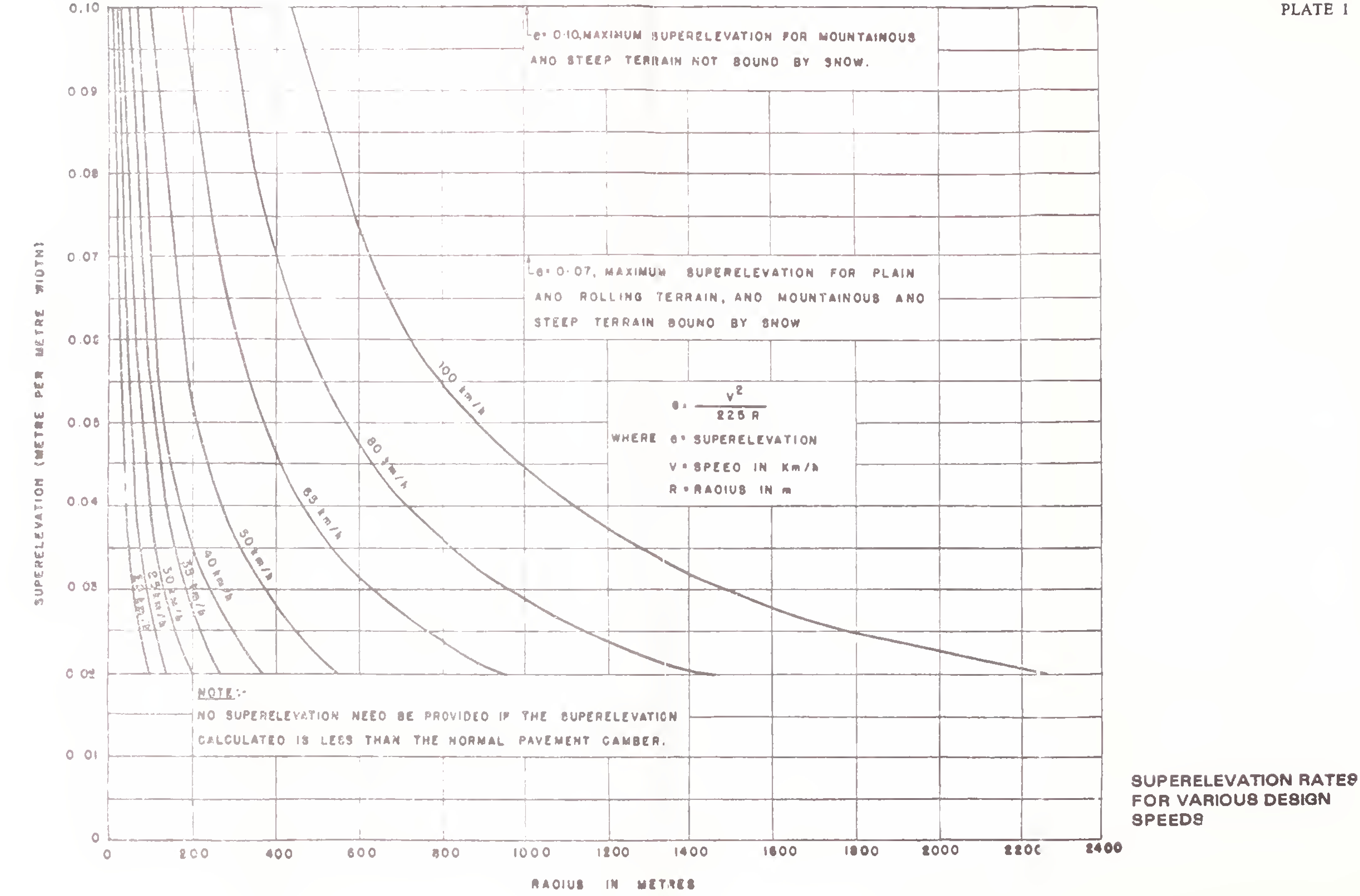
Superelevation required on horizontal curves should be calculated from the following formula. This assumes that centrifugal force corresponding to three-fourth the20
design speed is balanced by superelevation and rest counteracted by side friction:
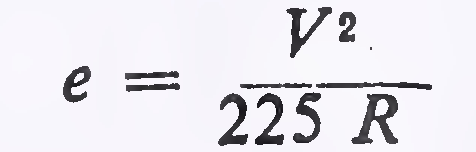
where
e = superelevation in metre per metre,
V = speed in km/h, and
R = radius in metres
Superelevation obtained from the above expression should however be kept limited to the following values:
| (a) In plain and oiling terrain | 7 per cent |
| (b) In snow-bound areas | 7 per cent |
| (c) In hilly areas not bound by snow | 10 per cent |
Plate 1 indicates the superelevation for various design speeds on this basis.
When the value of the superelevation obtained vide para 9.3.1 is less than the road camber, the normal cambered section should be continued on the curved portion without providing any superelevation. Table 15 shows the radii of horizontal curves for different camber rates beyond which superelevation will not be required.
| Design speed (km/h) | Radius (metres) for camber of | ||||
|---|---|---|---|---|---|
| 4 per cent | 3 per cent | 2.5 per cent | 2 per cent | 1.7 per cent | |
| 20 | 50 | 60 | 70 | 90 | 100 |
| 25 | 70 | 90 | 110 | 140 | 150 |
| 30 | 100 | 130 | 160 | 200 | 240 |
| 35 | 140 | 180 | 220 | 270 | 320 |
| 40 | 180 | 240 | 280 | 350 | 420 |
| 50 | 280 | 370 | 450 | 550 | 650 |
| 65 | 470 | 620 | 750 | 950 | 1100 |
| 80 | 700 | 950 | 1100 | 1400 | 1700 |
| 100 | 1100 | 1500 | 1800 | 2200 | 260021 |
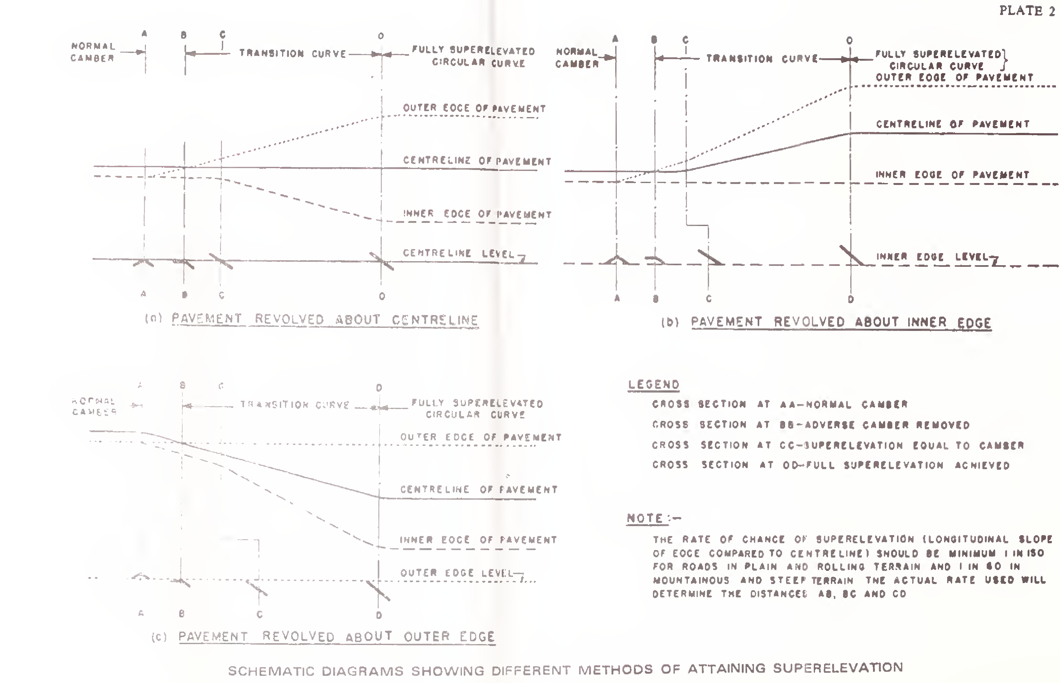
The normal cambered section of the road is changed into superelevated section in two stages. First stage is the removal of adverse camber in outer half of the pavement. In the second stage, superelevation is gradually built up over the full width of the carriageway so that required superelevation is available at the beginning of the circular curve. There are three different methods for attaining the superelevation: (i) revolving pavement about the centre line; (ii) revolving pavement about the inner edge; and (iii) revolving pavement about the outer edge. Plate 2 illustrates these methods diagrammatically. The small cross-sections at the bottom of each diagram indicate the pavement cross slope condition at different points.
Each of the above methods is applicable under different conditions. Method (i) which involves least distortion, of the pavement will be found suitable in most of the situations where there are no physical controls, and may be adopted in the normal course. Method (ii) is preferable where the lower edge profile is a major control, e.g. on account of drainage. Where overall appearance is the criterion, method (iii) is preferable since the outer edge profile which is most noticeable to drivers is not distorted.
The superelevation should be attained gradually over the full length of the transition curve so that the design superelevation is available at the starting point of the circular portion. Sketches in Plate 2 have been drawn on this basis. In cases where transition curve cannot for some reason be provided, two-third superelevation may be attained on the straight section before start of the circular curve and the balance one-third on the curve.
In developing the required superelevation, it should be ensured that the longitudinal slope of the pavement edge compared to the centre-line (i.e. the rate of change of superelevation) is not steeper than 1 in 150 for roads in plain and rolling terrain, and 1 in 60 in mountainous and steep terrain.
When cross-drainage structures fall on a horizontal curve, their deck should be superelevated in the same manner as described above.
On a horizontal curve, the centrifugal force is balanced by the combined effects of superelevation and side friction. The22
basic equation for this condition of equilibrium is: or 
where
| v | = vehicle speed in metre per second |
| V | = vehicle speed in km/h |
| g | = acceleration due to gravity in metre per see2 |
| e | = superelevation ratio in metre per metre |
| f | = coefficient of side friction between vehicle tyres and pavement (taken as 0.15) |
| R | = radius in metres |
Based on this equation and the maximum permissible values of superelevation given in para 9.3.1. radii for horizontal curves corresponding to ruling minimum and absolute minimum design speeds are shown in Table 16.
On new roads, horizontal curves should be designed to have the largest practicable radius; generally more than the values corresponding to the ruling design speed (see Table 16). However, absolute minimum values based on minimum design speed (Table 16) might be resorted to if economics of construction or the site conditions so dictate. While improving existing roads, curves having radii corresponding to absolute minimum standards may not be flattened unless it is necessary to realign the road for some other reasons.
Transition curves are necessary for a vehicle to have smooth entry from a straight section into a circular curve. The transition curves also improve aesthetic appearance of the road besides permitting gradul application of the superelevation and extra widening of carriageway needed at .the horizontal curves. Spiral curve should be used for this purpose.
Minimum length of the transition curve should be determined from the following two considerations and the larger of the two values adopted for design.23
| Classification of road | Plain terrain | Rolling terrain | Mountainous terrain | Steep terrain | ||||||||
|---|---|---|---|---|---|---|---|---|---|---|---|---|
| Areas not affected by snow | Snow bound areas | Areas not affected by snow | Snow bound areas | |||||||||
| Ruling Minimum | Absolute Minimum | Ruling Minimum | Absolute Minimum | Ruling Minimum | Absolute Minimum | Ruling Minimum | Absolute Minimum | Ruling Minimum | Absolute Minimum | Ruling Minimum | Absolute Minimum | |
| 1. National Highways and State Highways | 360 | 230 | 230 | 155 | 80 | 50 | 90 | 60 | 50 | 30 | 60 | 33 |
| 2. Major District Roads | 230 | 155 | 155 | 90 | 50 | 30 | 60 | 33 | 30 | 14 | 33 | 15 |
| 3. Other District Roads | 155 | 90 | 90 | 60 | 30 | 20 | 33 | 23 | 20 | 14 | 23 | 15 |
| 4. Village Roads | 90 | 60 | 60 | 45 | 20 | 14 | 23 | 15 | 20 | 14 | 23 | 15 |
|
Notes: 1. Absolute minimum and ruling minimum radii correspond to the minimum design speed and ruling design speed respectively vide Table 2. 2. For guidance in application, see para 9.4.2.24 | ||||||||||||
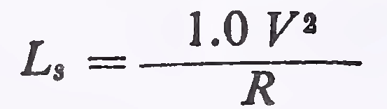
(i) The rate of change of centrifugal acceleration should not cause discomfort to drivers. From this consideration, the length of transition curve is given by:
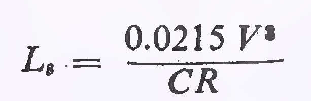
where
L8 = length of transition in metres
V = speed in km/h
R = radius of circular curve in metres
 (subject to a maximum of 0.8 and minimum of 0.5)
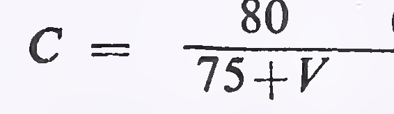
(ii) The rate of change of superelevation (i.e. the longitudinal grade developed at the pavement edge compared to through grade along the centre line) should be such as not to cause discomfort to travellers or to make the road appear unsightly. Rate of change should not be steeper than 1 in 150 for roads in plain and rolling terrain, and 1 in 60 in mountainous/steep terrain. The formulae for minimum length of transition on this basis are:
For Plain and Rolling Terrain:
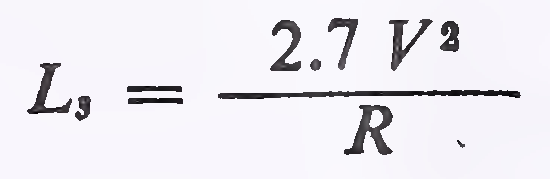
For Mountainous and Steep Terrain:
Having regard to the above considerations, the minimum transition lengths for different speeds and curve radii are given in Table 17.
The elements of a combined circular and transition curves are illustrated in Fig. 2. For deriving values of the individual elements like shift, tangent distance, apex distance etc. and working out coordinates to lay the curves in the field, it is convenient to use curve tables. For this, reference may be made to IRC: 38 “Design Tables for Horizontal Curves for Highways”.
At sharp horizontal curves, it is necessary to widen the carriageway to provide for safe passage of vehicles. The widening required has two components: (i) mechanical widening to compen-25
| Plain and rolling terrain | Mountainous and steep terrain | |||||||||||
|---|---|---|---|---|---|---|---|---|---|---|---|---|
| Curve radius R (metres) |
Design speed (km/h) | Curve radius (metres) |
Design speed (km/h) | |||||||||
| 100 | 80 | 65 | 50 | 40 | 35 | 50 | 40 | 30 | 25 | 20 | ||
| Transition length—metres | Transition length—metres | |||||||||||
| 45 | NA | 70 | 14 | NA | 30 | |||||||
| 60 | NA | 75 | 55 | 20 | 35 | 20 | ||||||
| 90 | 75 | 50 | 40 | 25 | NA | 25 | 20 | |||||
| 100 | NA | 70 | 45 | 35 | 30 | 30 | 25 | 15 | ||||
| 150 | 80 | 45 | 30 | 25 | 40 | NA | 25 | 20 | 15 | |||
| 170 | 70 | 40 | 25 | 20 | 50 | 40 | 20 | 15 | 15 | |||
| 200 | NA | 60 | 35 | 25 | 20 | 55 | 40 | 20 | 15 | 15 | ||
| 240 | 90 | 50 | 30 | 20 | NR | 70 | NA | 30 | 15 | 15 | 15 | |
| 300 | NA | 75 | 40 | 25 | NR | 80 | 55 | 25 | 15 | 15 | NR | |
| 360 | 130 | 60 | 35 | 20 | 90 | 45 | 25 | 15 | 15 | |||
| 400 | 115 | 55 | 30 | 20 | 100 | 45 | 20 | 15 | 15 | |||
| 500 | 95 | 45 | 25 | NR | 125 | 35 | 15 | 15 | NR | |||
| 600 | 80 | 35 | 20 | 150 | 30 | 15 | 15 | |||||
| 700 | 70 | 35 | 20 | 170 | 25 | 15 | NR | |||||
| 800 | 60 | 30 | NR | 200 | 20 | 15 | ||||||
| 900 | 55 | 30 | 250 | 15 | 15 | |||||||
| 1000 | 50 | 30 | 300 | 15 | NR | |||||||
| 1200 | 40 | NR | 400 | 15 | ||||||||
| 1500 | 35 | 500 | NR | |||||||||
| 1800 | 30 | |||||||||||
| 2000 | NR | |||||||||||
|
NA—Not applicable NR—Transition not required26 | ||||||||||||
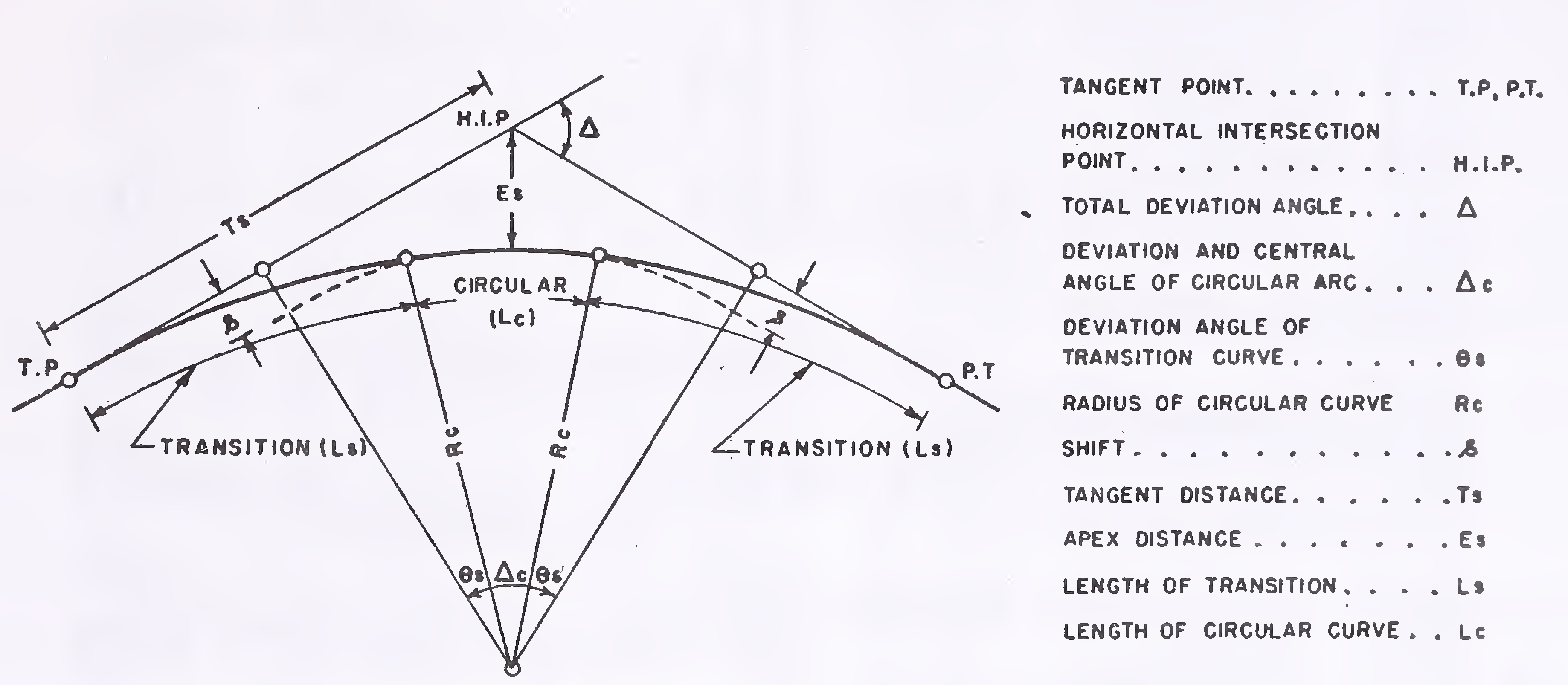
Fig. 2. Elements of a combined circular and transition curve27
sate the extra width occupied by a vehicle on the curve due to tracking of the rear wheels, and (ii) psychological widening to permit easy crossing of vehicles since vehicles in a lane tend to wander more on a curve than on a straight reach.
On two-lane or wider roads it is necessary that both, the above components should be fully catered for so that the lateral clearance between vehicles on curves is maintained equal to the clearance available on straights. Position of single-lane roads however is somewhat different, since during crossing manoeuvres outer wheels of vehicles have in any case to use the shoulders whether on the straight or on the curve. It is therefore sufficient on single-lane roads if only the mechanical component of widening is taken into account.
Based on the above considerations, the extra width of carriageway to be provided at horizontal curves on single and two-lane roads is given in Table 18. For multi-lane roads, the pavement widening may be calculated by adding half the widening for two-lane roads to each lane.
|
Radius of curve (m) Extra width (m) |
Upto 20 | 21 to 40 | 41 to 60 | 61 to 100 | 101 to 300 | Above 300 |
|---|---|---|---|---|---|---|
| Two-lane | 1.5 | 1.5 | 1.2 | 0.9 | 0.6 | Nil |
| Single-lane | 0.9 | 0.6 | 0.6 | Nil | Nil | Nil |
The widening should be effected by increasing the width at an approximately uniform rate along the transition curve. The extra width should be continued over the full length of the circular curve. On curves having no transition, widening should be achieved in the same way as the superelevation i.e. two-third being attained on the straight section before start of the curve and one-third on the curve.
The widening should be applied equally on both sides of the carriageway, except that on hill roads it will be preferable if the entire widening is done only on the inside. Similarly, the widening should be provided only on the inside when the curve is plain circular and has no transition.28
The extra widening may be attained by means of offsets radial to the centre line. It should be ensured that the pavement edge lines are smooth and there is no apparent kink.
Requisite sight distance should be available across the inside of horizontal curves. Lack of visibility in the lateral direction may arise due to obstructions like walls, cut slopes, buildings, wooded areas, high farm crops etc. Distance from the road centre line within which the obstructions should be cleared to ensure the needed visibility, i.e. the “set-back distance”, can be calculated vide procedure described in para 9.7.2. But in certain cases, due to variations in alignment, road cross-section, and the type and location of obstructions, it may become necessary to resort to field measurements to determine the limits of clearance.
The set-back distance is calculated from the following equation (see Fig. 3 for definitions):
where 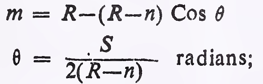
m = the minimum set-back distance to sight obstruction in metres (measured from the centre line of the road);
R = radius at centre line of the road in metres;
n = distance between the centre line of the road and the centre line of the inside lane in metres; and
S = sight distance in metres
In the above equation, sight distance is measured along the middle of inner lane. On single-lane roads, sight distance is measured along centre line of the road and ′n' is taken as zero.
Based on the above equation, design charts for set′back distance corresponding to the safe stopping sight distance are given in Fig. 4.
Set-back distance for overtaking or intermediate sight distance can be computed similarly but the clearance required is usually too large to be economically feasible except on very flat curves.
When there is a cut slope on the inside of the horizontal curve, the average height of sight line can be used as an approximation for deciding the extent of clearance. For stopping sight29
Fig. 3. Visibility at horizontal curves30
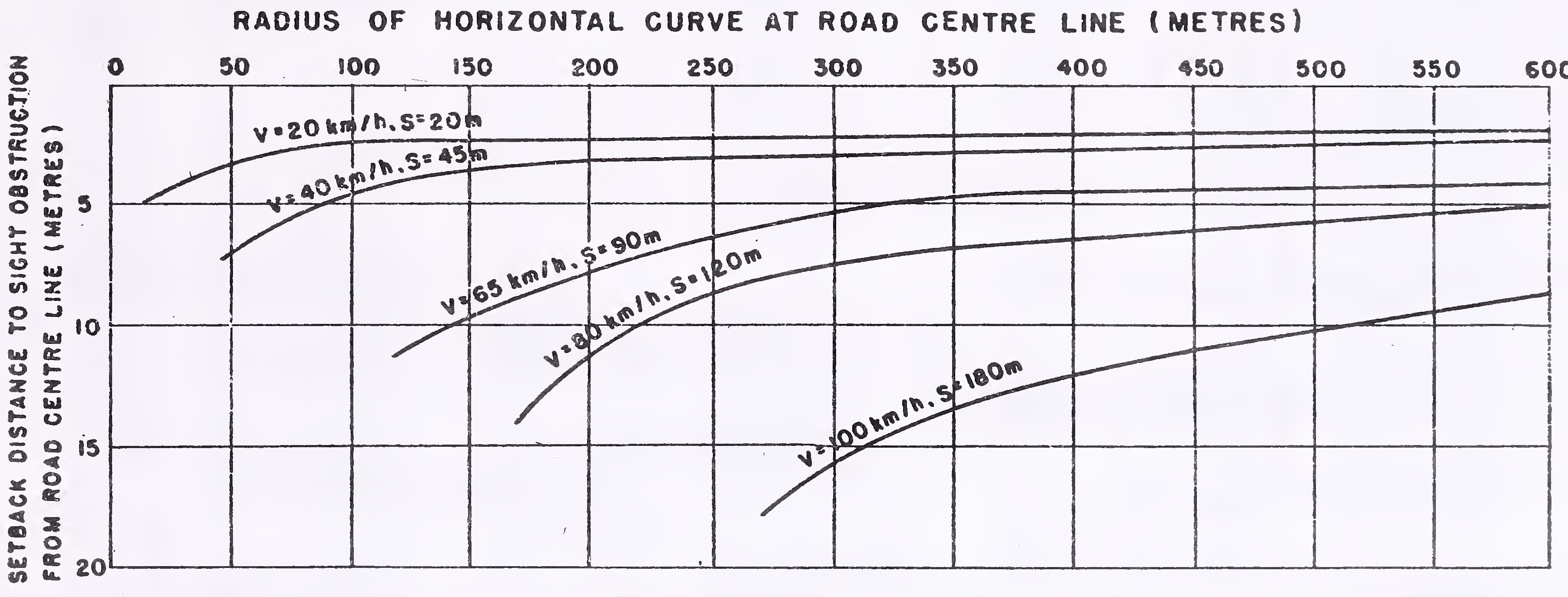
Fig. 4. Minimum set-back distance required at horizontal curves for safe stopping sight distance31
distance, which is the bare minimum requirement for design, the average height may be taken as 0.7 m. Cut slopes should be kept lower than this height at the line demarcating the set-back distance envelope, either by cutting back the slope or benching suitably. In the case of intermediate or overtaking sight distance, height of sight line above the ground should be taken as 1.2 m.
Where horizontal and summit vertical curves overlap, the design should provide for the required sight distance both in the vertical direction along the pavement and in the horizontal direction on the inside of the curve.
In hilly areas it may become difficult to avoid bends where direction of the road reverses. Design criteria for such bends, commonly known as the hair-pin bends, are dealt with in' para 10.5.
The vertical alignment should provide for a smooth longitudinal profile consistent with category of the road and lay of the terrain. Grade changes should not be too frequent as to cause kinks and visual discontinuities in the profile. Desirably, there should be no change in grade within a distance of 150 m.
A short valley curve within an otherwise continuous profile is undesirable Since this tends to distort the perspective view and can be hazardous.
Broken-back grade lines, i.e. two vertical curves in the same direction separated by a short tangent, should be avoided due to poor appearance and preferably replaced by a single long curve.
Decks of small cross-drainage structures, (i.e. culverts and minor bridges) should follow the same profile as the flanking road section, without any break in the grade line.
The longitundinal profile should be co-ordinated suitably with the horizontal alignment. This is discussed in Section II.
Grades should be carefully selected keeping in view the design speed, terrain conditions and nature of traffic expected32
on the road. It is difficult and costly to flatten the gradients later.
Recommended gradients for different classes of terrain are given in Table 19.
| S. No. | Terrain | Ruling gradient | Limiting gradient | Exceptional gradient |
|---|---|---|---|---|
| 1. | Plain or rolling | 3.3 per cent (1 in 30) |
5 per cent (1 in 20) |
6.7 per cent (1 in 15) |
| 2. | Mountainous terrain, and steep terrain having elevation more than 3,000 m above the mean sea level | 5 per cent (1 in 20) |
6 per cent (1 in 16.7) |
7 per cent (1 in 14.3) |
| 3. | Steep terrain upto 3,000 m height above mean sea level |
6 per cent (1 in 16.7) |
7 per cent (1 in 14.3) |
8 per cent (1 in 12.5) |
Gradients upto the ‘ruling gradient’ may be used as a matter of course in design. However in special situations such as isolated over-bridges in flat country or roads carrying a large volume of slow moving traffic, it will be desirable to adopt a flatter gradient of 2 per cent from the angle of aesthetics, traffic operations, and safety.
The ‘limiting gradients’ may be used where the topography of a place compels this course or where the adoption of gentler gradients would add enormously to the cost. In such cases, the length of continuous grade steeper than the ruling gradient should be as short as possible.
‘Exceptional gradients’ are meant to be adopted only in very difficult situations and for short lengths not exceeding 100 m at a stretch. In mountainous and steep terrain, successive stretches of exceptional gradients must be separated by a minimum length of 100 m having gentler gradient (i.e. limiting gradient or flatter).
The rise in elevation over a length of 2 km shall not exceed 100 m in mountainous terrain and 120 m in steep terrain.
On unkerbed pavements in embankment, near-level grades are not objectionable when the pavement has sufficient camber to drain the storm water33
laterally. However, in cut sections or where the pavement is provided with kerbs, it is necessary that the road should have some gradient for efficient drainage. Desirable minimum gradient for this purpose is 0.5 per cent if the side drains are lined and 1.0 per cent if these are unlined.
At horizontal curves, the gradients should be eased by an amount known as the ‘grade compensation’ which is intended to offset the extra tractive effort involved at curves. This should be calculated from the following formula:
Grade compensation (per cent) = 
subject to a maximum of 75/R where R is the radius of the curve in metres.
Since grade compensation is not necessary for gradients flatter than 4 per cent, when applying grade compensation correction, the gradients need not be eased beyond 4 per cent.
Vertical curves are introduced for smooth transition at grade changes.. Convex vertical curves are known as summit curves and concave vertical curves as valley or sag curves. Both these should be designed as square parabolas.
The length of the vertical curves is controlled by sight distance requirements, but curves with greater length are aesthetically better.
Curves should be provided at all grade changes exceeding those indicated in Table 20. For satisfactory appearance, the minimum length should be as shown in the Table.
| Design speed (km/h) | Maximum grade change (per cent) not requiring a vertical curve | Minimum length of vertical curve (metres) |
|---|---|---|
| Upto 35 | 1.5 | 15 |
| 40 | 1.2 | 20 |
| 50 | 1.0 | 30 |
| 65 | 0.8 | 40 |
| 80 | 0.6 | 50 |
| 100 | 0.5 | 6034 |
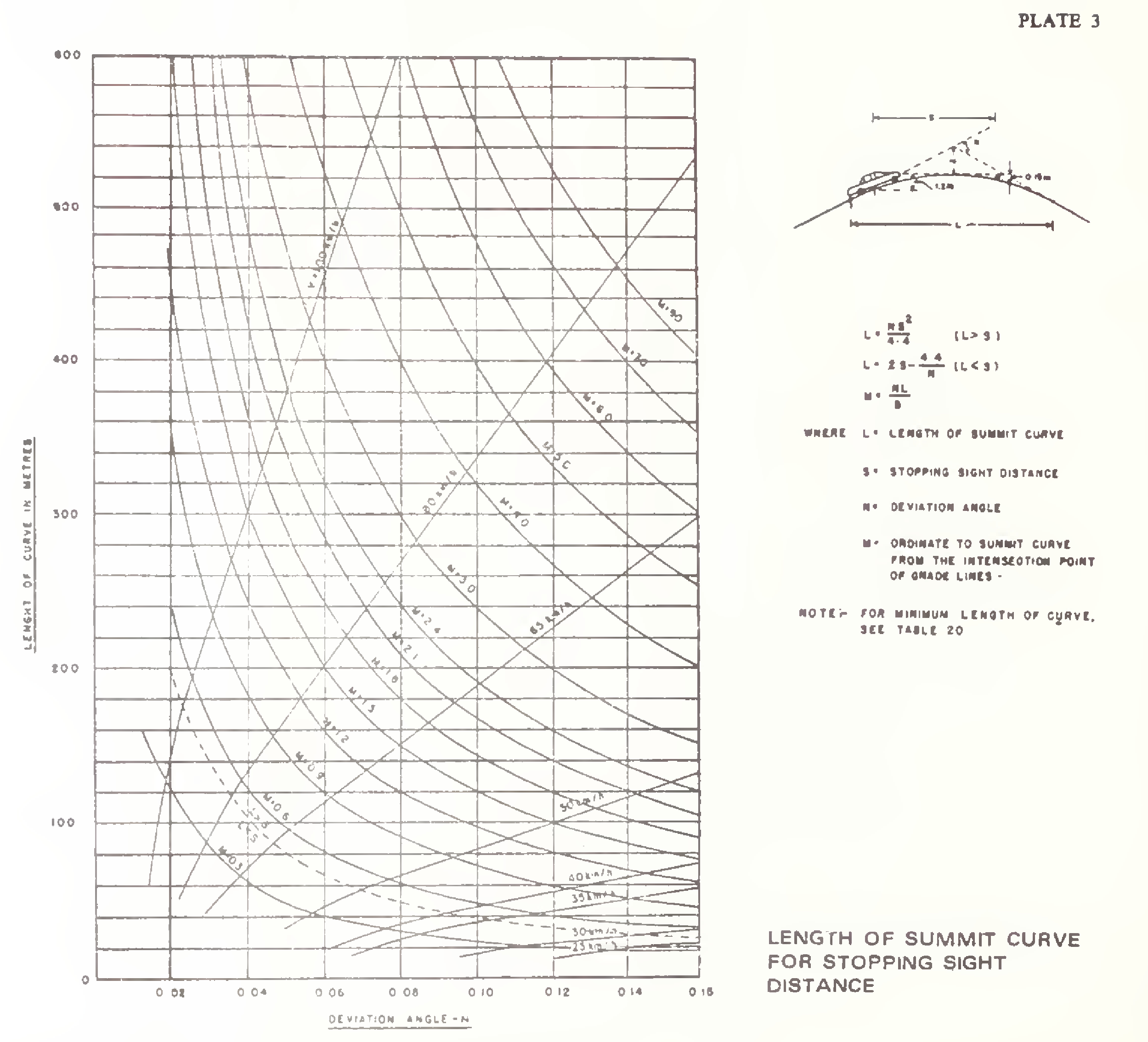
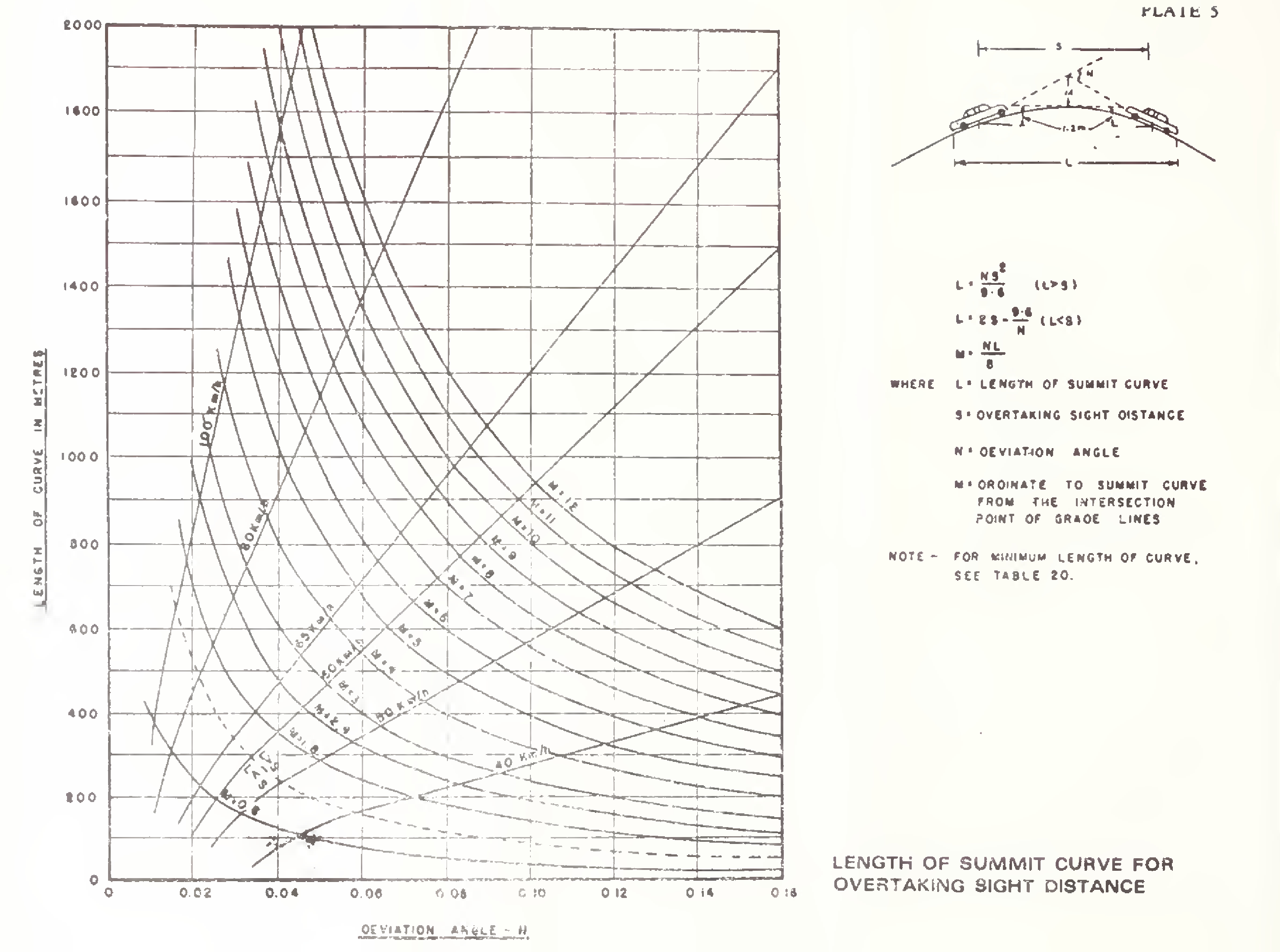
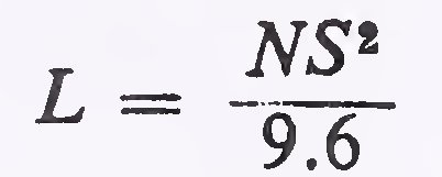
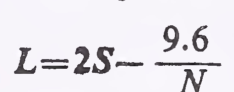
The length of summit curves is governed by the choice of sight distance. The length is calculated on the basis of the following formulae:
(a)For safe stopping sight distance
Case (i) When the length of the curve exceeds the required sight distance, i.e. L is greater than S

where N = deviation angle, i.e. the algebraic difference between the two grades
L = length of parabolic vertical curve in metres
S = sight distance in metres
Case (ii) When the length of the curve is less than the required sight distance, i.e. L is less than S
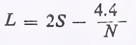
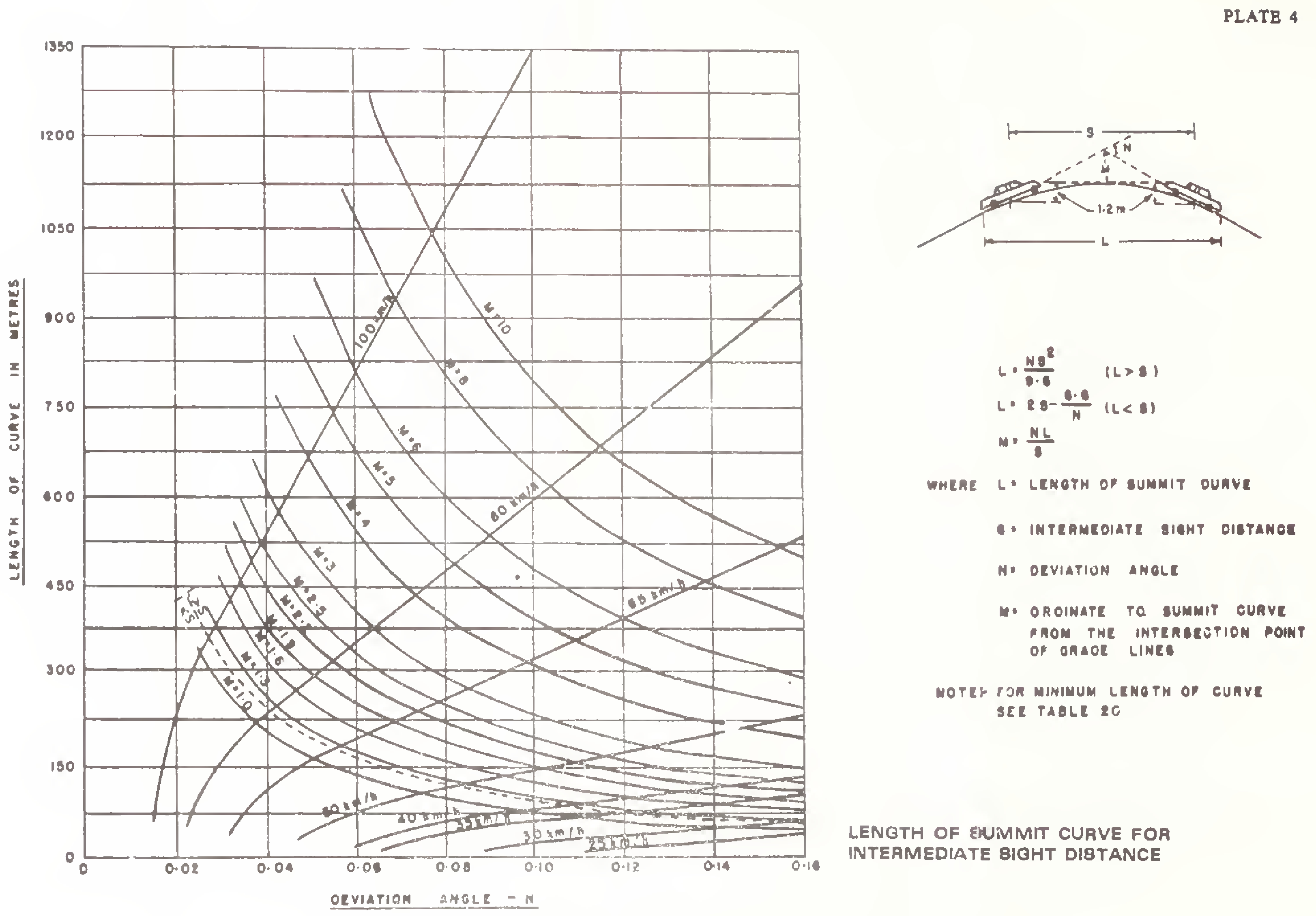
(b)For intermediate or overtaking sight distance
Case (i) When the length of the curve exceeds the required sight distance, i.e. L is greater than S
Case (ii) When the length of the curve is less than the required sight distance, i.e. L is less than S
The length of summit curve for various cases mentioned above can be read from Plates 3, 4 and 5. In these Plates, value of the ordinate “M“ to the curve from the intersection point of grade lines is also shown.
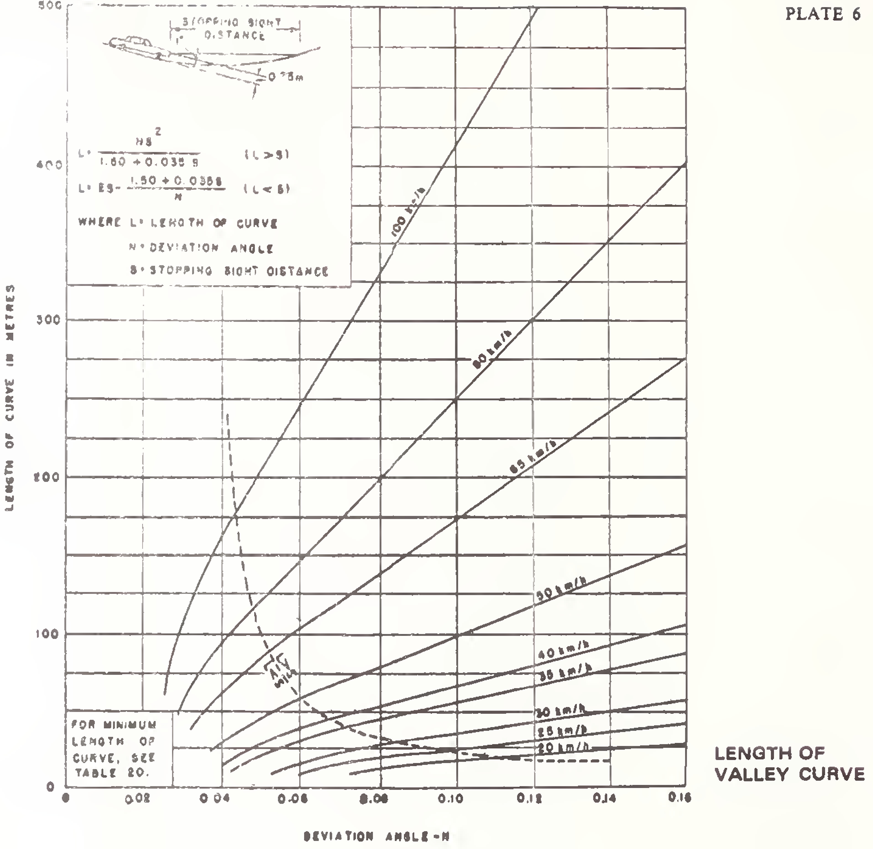
The length of.valley curves should be such that for night travel, the headlight beam distance is equal to the. stopping sight35
distance. The length of curve may be calculated as under:
Case (i) When the length of the curve exceeds the required sight distance, i.e. L is greater than S

Case (ii) When the length of the curve is less than the required sight distance, i.e. L is less than S

In both cases
N = deviation angle, i.e. the algebraic difference between the two grades
L = length of parabolic vertical curve in metres
S = stopping sight distance in metres
Length of valley curve for various grade differences is given in graphical form in Plate 6.
Hair-pin bends, where unavoidable, may be designed either as a circular curve with transition at each end, or as a compound circular curve. The following criteria should be followed normally for their design:
| (a) | Minimum design speed | ... | 20 km/h |
| (b) | Minimum roadway width at apex | ||
| (i) National/State Highways | ... | 11.5 m for double-lane 9.0 m for single-lane |
|
| (ii) Major District Roads and Other District Roads | ... | 7.5 m | |
| (iii) Village Roads | ... | 6.5 m | |
| (c) | Minimum radius for the inner curve | ... | 14.0 m |
| (d) | Minimum length of transition curve | ... | 15.0 m |
| (e) | Gradient | ||
| Maximum | ... | 1 in 40 (2.5 per cent) | |
| Minimum | ... | 1 in 200 (0.5 per cent) | |
| (f) | Superelevation | ... | 1 in 10 (10 per cent) |
Inner and outer edges of the roadway should be concentric with respect to centre line of the pavement. Where a36
number of hair-pin. bends have to be introduced, a minimum intervening distance of 60 m should be provided between the successive bends to enable the driver to negotiate the alignment smoothly.
Widening of hair-pin bends subsequently is a difficult and costly process. Moreover, gradients tend to become sharper as generally widening can be achieved only by cutting the hill side. These points should be kept in view at the planning stage, especially if a series of hair-pin bends is involved.
At hair-pin bends, preferably the full roadway width should be surfaced.
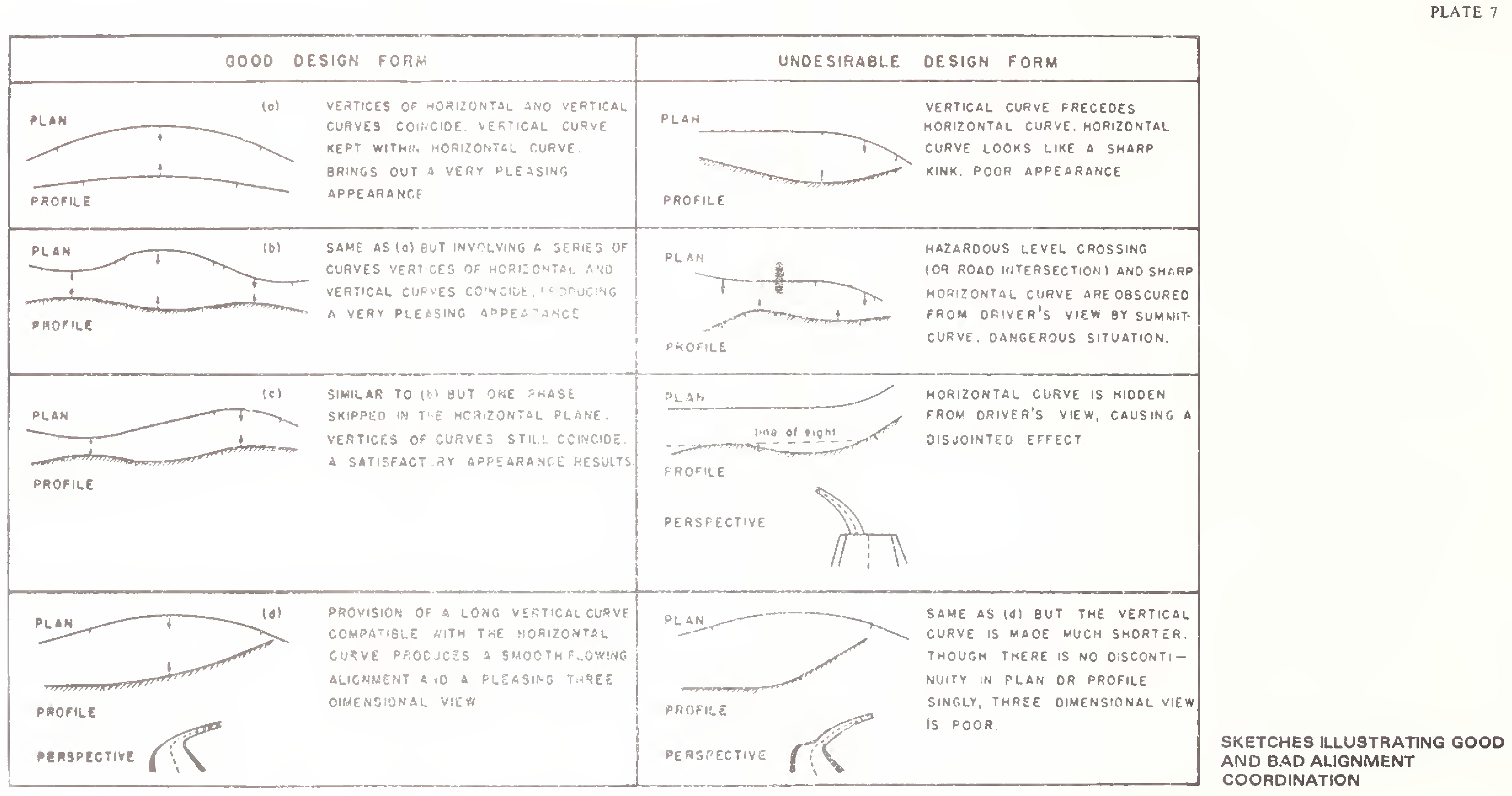
The overall appearance of a highway can be enhanced considerably by judicious combination of the horizontal and vertical alignments. Plan and profile of the road should not be designed independently but in unison so as to produce an appropriate threedimensional effect. Proper co-ordination in this respect will ensure safety, improve utility of the highway and contribute to overall aesthetics.
The degree of curvature should be in proper balance with the gradients. Straight alignment or flat horizontal curves at the expense of steep or long grades, or excessive curvature in a road with flat grades, do not constitute balanced designs and should be avoided.
Vertical curvature superimposed upon horizontal curvature gives a pleasing effect. As such the vertical and horizontal curves should coincide as far as as possible and their length should be more or less equal. If this is difficult for any reason, the horizontal curve should be somewhat longer than the vertical curve.
Sharp horizontal curves should be avoided at or near the apex of pronounced summit/sag vertical curves from safety considerations.
Plate 7 illustrates some typical cases of good and bad alignment co-ordination.
Lateral Clearance
Desirably the full roadway width at the approaches should be carried through the underpass. This implies that the37
minimum lateral clearance (i.e. the distance between the extreme edge of the carriageway and the face of nearest support, whether a solid abutment, pier or column) should equal the normal shoulder width.
On lower category roads in hill areas having comparatively narrow shoulders, it will be desirable to increase the roadway width at underpasses to a certain extent keeping in view para 6.3. and the principles set forth in IRC:54-1974 “Lateral and Vertical Clearances at Underpasses for Vehicular Traffic”
For desirable lateral clearances at dual carriageway roads, reference may be made to IRC:54-1974.
Vertical clearance at underpasses should be minimum 5 metres after making due allowance for any future raising/streng-thening of the underpass roadway.38