This library of books, audio, video, and other materials from and about India is curated and maintained by Public Resource. The purpose of this library is to assist the students and the lifelong learners of India in their pursuit of an education so that they may better their status and their opportunities and to secure for themselves and for others justice, social, economic and political.
This item has been posted for non-commercial purposes and facilitates fair dealing usage of academic and research materials for private use including research, for criticism and review of the work or of other works and reproduction by teachers and students in the course of instruction. Many of these materials are either unavailable or inaccessible in libraries in India, especially in some of the poorer states and this collection seeks to fill a major gap that exists in access to knowledge.
For other collections we curate and more information, please visit the Bharat Ek Khoj page. Jai Gyan!
IRC:5-1998
General Features of Design
(Seventh Revision)
Published by
THE INDIAN ROADS CONGRESS
Jamnagar House, Shahjahan Road,
New Delhi-110 011
1998
Price Rs. 160/-
(Plus Packing & Postage)
MEMBERS OF THE BRIDGE SPECIFICATIONS AND STANDARDS COMMITTEE
(As on 12.3.97)
| 1. | A.D. Narain* (Convenor) |
DG(RD) & Addl. Secretary to the Govt. of India, Ministry of Surface Transport (Roads Wing), Transport Bhawan, New Delhi-110001 |
| 2. | The Chief Engineer (B) S&R (Member-Secretary) |
Ministry of Surface Transport (Roads Wing), Transport Bhawan, New Delhi-110001 |
| 3. | S.S. Chakraborty | Managing Director, Consulting Engg. Services (I) Pvt. Ltd., 57, Nehru Place, New Delhi-110019 |
| 4. | Prof. D.N. Trikha | Director, Structural Engg. Res. Centre, Sector-19, Central Govt. Enclave, Kamla Nehru Nagar, PB No. 10, Ghaziabad-201002 |
| 5. | Ninan Koshi | DG(RD) & Addl. Secretary (Retd.), 56, Nalanda Apartments, Vikaspuri, New Delhi |
| 6. | The Chief Engineer (NH) | Punjab PWD, B&R Branch, Patiala |
| 7. | A.G. Borkar | Technical Adviser to Metropolitan Commr. A-l, Susnehi Plot No. 22, Arun Kumar Vaidya Nagar, Bandra Reclamation, Mumbai-400050 |
| 8. | N.K. Sinha | Chief Engineer (PIC), Ministry of Surface Transport (Roads Wing), Transport Bhawan, New Delhi-110001 |
| 9. | The Director General (Works) | Central Public Works Department, Nirman Bhavan, New Delhi |
| 10. | The Secretary to the Govt. of Gujarat | (Shri H.P. Jamdar) R&B Department, Block No. 14, New Sachivalaya, 2nd Floor, Gandhinagar-382010 |
| 11. | The Chief Engineer (R&B) | (Shri D. Sree Rama Murthy) National Highways, Irrum Manzil, Hyderabad-500482 |
| 12. | M.V.B. Rao | Head, Bridges Division, Central Road Res. Institute, P.O. CRRI, Delhi-Mathura Road. New Delhi-110020 |
| 13. | C.R. Alimchandani | Chairman & Managing Director, STUP Consultants Ltd., 1004-5, Raheja Chambers, 213. Nariman Point, Mumbai-400021i |
| 14. | Dr. S.K. Thakkar | Professor, Department of Earthquake Engg., University of Roorkee, Roorkee-247667 |
| 15. | M.K. Bhagwagar | Consulting Engineer, Engg Consultants (P) Ltd., F-14/15, Connaught Place, Inner Circle, 2nd Floor, New Delhi-110001 |
| 16. | The Engineer-in-Chief | (Shri K.B. Lal Singal), Haryana P.W.D., B&R, Sector-19 B, Chandigarh-160019 |
| 17. | P.D. Wani | Secretary to the Govt. of Maharashtra, P.W.D., Mantralaya, Mumbai-400032 |
| 18. | S.A. Reddi | Dy. Managing Director, Gammon India Ltd., Gammon House, Veer Savarkar Marg, Prabhadevi, Mumbai-400025 |
| 19. | Vijay Kumar | General Manager, UP State Bridge Corpn. Ltd. 486, Hawa Singh Block, Asiad Village, New Delhi-110049 |
| 20. | C.V. Kand | Consultant, E-2/136, Mahavir Nagar, Bhopal-462016 |
| 21. | M.K. Mukherjee | 40/182, C.R. Park, New Delhi-110019 |
| 22. | Mahesh Tandon | Managing Director, Tandon Consultants (P) Ltd.. 17, Link Road, Jangpura Extn., New Delhi |
| 23. | Dr. T.N. Subba Rao | Chairman, Construma Consultancy (P) Ltd., 2nd Floor, Pinky Plaza, 5th Road, Khar (West) Mumbai-400052 |
| 24. | The Chief Engineer (R) S&R | (Shri lndu Prakash), Ministry of Surface Transport (Roads Wing), Transport Bhawan, New Delhi-110001 |
| 25. | The Director | Highways Research Station, 76, Sarthat Patel Road, Chennai-600025 |
| 28. | A.K. Harit | Executive Director (B&S), Research Designs & Standards Organisation, Lucknow-226011 |
| 29. | The Director & Head | (Shri Vinod Kumar), Bureau of Indian Standard Manak Bhavan, 9, Bahadurshah Zarfar Marg, New Delhi-110002 |
| 30. | Prafulla Kumar | Member (Technical), National Highway Authority of India, Eastern Avenue, Maharani Bagh, New Delhi-110065 |
| 31. | S.V.R. Parangusam | Chief Engineer (B) South, Ministry of Surface Transport (Roads Wing), Transport Bhawan, New Delhiii |
| 32. | The Chief Engineer (NH) | (Shri D. Guha), Public Works Department. Writers Building, Block C, Calcutta-700001 |
| 33. | The Chief Engineer (NH) | M.P. Public Works Department, Bhopal-462004 |
| 34. | The Chief Engineer (NH) | (Shri P.D. Agarwal), U P. PWD, PWD Quarters Kabir Marg Clay Square, Lucknow-226001 |
| 35. | B.C. Rao | Offg DDG (Br.), Dy Director General (B), West Block-IV, Wing l, R.K. Puram, New Delhi-110066 |
| 36. | P.C. Bhasin | 324, Mandakini Enclave, Alkananda, New Delhi-110019 |
| 37. | P.K. Sarmah | Chief Engineer, PWD (Roads) Assam, P.O. Chandmari, Guwahati-781003 |
| 38. |
President, Indian Roads Congress | H P. Jamdar, Secretary to the Govt. of Gujarat, R&B Department, Sachivalaya, 2nd Floor, Gandhinagar-382010 - Ex-Officio |
| 39. | Hon. Treasurer Indian Roads Congress |
A.D. Narain, DG(RD) & Addl. Secretary to the Govt. of India, Ministry of Surface Transport (Roads Wing), Transport Bhawan, New Delhi - Ex-Officio |
| 40. |
Secretary, Indian Roads Congress | S.C. Sharma, Chief Engineer, Ministry of Surface Transport (Roads Wing), Transport Bhawan, New Delhi - Ex-Officio |
| Corresponding Members | ||
| 1. | N.V. Merani | Principal Secretary (Retd.), A-47/1344, Adarsh Nagar, Worli, Mumbai |
| 2. | Dr. G.P. Saha | Chief Engineer, Hindustan Construction Co. Ltd., Hincon House, Lal Bahadur Shastri Marg, Vikhroli (W), Mumbai-400083 |
| 3. | Shitala Sharan | Advisor Consultant, Consulting Engg. Services (I) Pvt. Ltd., 57, Nehru Place,New Delhi-110019 |
| 4. | Dr. M.G. Tamhankar | Emeritus Scientist, Structural Engg. Res. Centre 399, Pocket E, Mayur Vihar, Phase II, Delhi -110091iii |
| * |
ADG(B) being not in position. The meeting was presided by Shri A.D. Narain. DG(RD) & Addl. Secretary to the Govt. of India, Ministry of Surface Transport |
|
GENERAL FEATURES OF DESIGN
The Bridge Code in outline form was originally drafted in 1944-45 by the Bridges Sub-Committee. The Code was redrafted by the Office of the Consulting Engineer (Roads) in consultation with the members of the Bridges Committee and was circulated to the Chief Engineers of the Public Works Departments of all States in India. It was also discussed at the Indian Roads Congress Session at Jaipur held in 1946. An expanded Bridges Committee modified the draft in the light of the comments received from the Chief Engineers of States, the discussions at the Jaipur Session and the discussions at the Bridges Committee meeting held from time to time and this Code was first published in January, 1956.
Some changes had later been approved by the Bridges Committee in the light of subsequent discussions at the Committee meetings. The Second and Third Revisions were published including the approved changes.
The Executive Committee of the Indian Roads Congress approved the publication of the Fourth Revision in metric units. This Code was revised by the Bridges Committee, and was later published as the Fifth Revision.
Subsequently the Sixth revision was brought out based on the provisions contained in IRC:78-1983, Standard Specifications and Code of Practice for Road Bridges, Section VII - Foundations and substructure.
The General Design Features Committee (B-2) (personnel given below) in its meeting held on 21.11.96 finalised the draft "General Features1
of Designs" (7th Revision).
| A.D. Narain | .. Convenor |
| A.K. Banerjee | .. Member-Secretary |
| Members | |
| S.S. Chakraborty | G.R. Haridas |
| D.T. Grover | M.K. Mukherjee |
| D.K. Kanhere | A. Chattopadhyaya |
| S.B. Kulkami | P.L. Manickam |
| M.R. Kachhwaha | CE (Design), PWD, Gujarat |
| A.K. Saxena | P.K. Saikia |
| B.K. Mittal | N.C. Saxena |
| Vijay Kumar | A.K. Mookerjee |
| Dr. B.P. Bagish | Dr. G.P. Saha |
| Corresponding Members | |
| B.C. Roy | S. Sengupta |
| Ex-Officio Members | |
| The President, IRC (M.S. Guram) |
The DG(RD) (A.D. Narain) |
| The Secretary, IRC (S C. Sharrna) |
|
The Draft was approved by the Bridge Specifications and Standards Committee and the Executive Committee in their meetings held on 12.3.97 and 29.3.97 respectively.
The draft was approved by the Council in their meeting held at Aizawl on 17.4.97.
This publication is meant to serve as a guide for engineers, engaged in the design and/or construction of road bridges. The provisions herein shall be used with discretion and care shall be taken to ensure that the stability and soundness of the structures designed and/or constructed as per these provisions are satisfactory.
The design and construction of road bridges require an extensive and thorough knowledge of the science and technique involved and should be entrusted only to specially qualified engineers with adequate practical experience in bridge engineering and capable of ensuring careful execution of work.2
This Code deals with the general features of design of road bridges and the recommendations of this Code shall apply to all types of bridges constructed for use by road traffic or other moving loads.
The following definitions shall be applicable for the purpose of this and other sections of the IRC Standard Specifications and Code of Practice for Road Bridges.
Bridge is a structure having a total length of above 6 metres between the inner faces of the dirt walls for carrying traffic or other moving loads over a depression or obstruction such as channel, road or railway. These bridges are classified as minor and major bridges as per classification given below :
| (a) Minor Bridge | : | A minor bridge is a bridge having a total length of upto 60 m. |
| (b) Major Bridge | : | A major bridge is a bridge having a total length of above 60 m. |
Bridges shall be graded as important essentially on the basis of the seriousness of the consequences of their distress/failure and the extent of remedial measures involved.
Culvert is a cross-drainage structure having a total length of 6 metres or less between the inner faces of the dirt walls or extreme ventway boundaries measured at right angles thereto.
A foot bridge is a bridge exclusively used for carrying pedestrians, cycles and animals.
A high level bridge is a bridge which carries the roadway above the highest flood level of the channel.
A submersible bridge/vented causeway is a bridge designed to be overtopped during floods.
A channel means a natural or artificial water course.
Clearance is the shortest distance between the boundaries at a specified position of a bridge structure.
Freeboard at any point is the difference between the highest flood level after allowing for afflux, if any, and the formation level of road embankment on the approaches or top level of guide bunds at that point.
Highest flood level is the level of the highest flood ever recorded or the calculated level for the design discharge.
Low water level is the level of the water surface obtaining generally in the dry season and shall be specified in case of each bridge.
The length of a bridge structure will be taken as the overall length measured along the centre line of the bridge between inner faces of dirtwalls.
Linear waterway of a bridge is the width of the waterway between the extreme edges of water surface at the highest flood level measured at right angles to the abutment faces.
Effective linear waterway is the total width of the waterway of the bridge at HFL minus the effective width of obstruction. The effective width of obstruction is to be worked out as per Clause No. 104.6.4
A safety kerb is a roadway kerb for occasional use of pedestrian traffic.
The width of carriageway is the minimum clear width measured at right angles to the longitudinal centre line of the bridge between the inside faces of roadway kerbs or wheel guards.
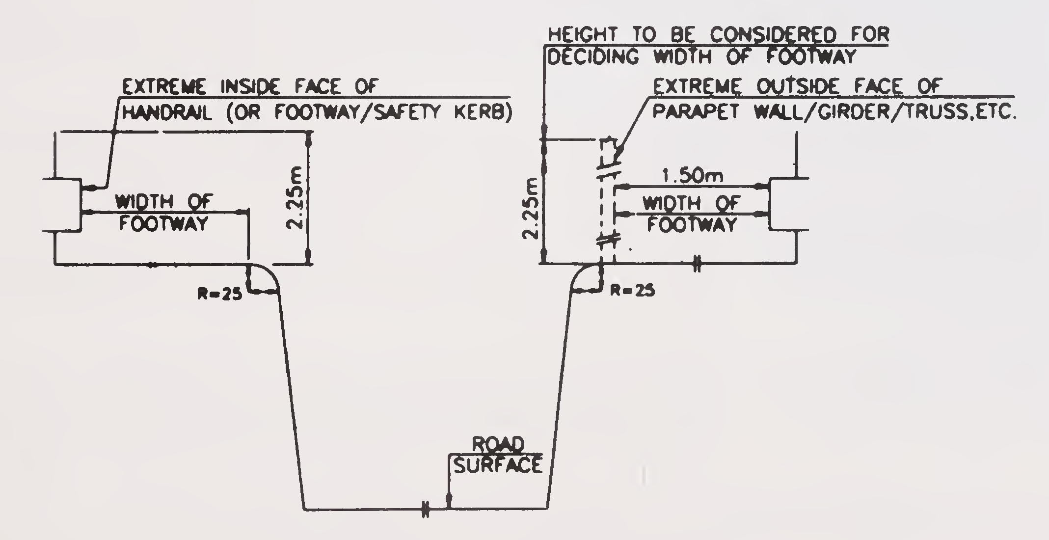
The width of footway or safety kerb shall be taken as the minimum clear width any where within a height of 2.25 metres above the surface of the footway or safety kerb, such width being measured at right angles to the centre line of the bridge, Fig. 1.
Fig. 1. Width of Footway (Clause 101.12)
Super elevation is the transverse inclination given to the cross-section of a carriageway on a horizontal curve in order to reduce the effects of centrifugal force on a moving vehicle.5
All detailed information for a complete and proper appreciation of the bridge project shall be included in the project documents. Generally the following information shall be furnished.
An index map to a suitable small scale (toposheets in scale one cm to 500 m or 1/50,000 would do in most cases) showing the proposed location of the bridge, the alternative sites investigated and rejected, the existing means of communication, the general topography of the country and the important towns, villages etc. in the vicinity.
A contour survey plan of the stream showing all topographical features and extending upstream and downstream of any of the proposed sites, to the distances shown below, (or such other greater distances as the engineer responsible for the design may direct) and to a sufficient distance on either side to give a clear indication of the topographical or other features that might influence the location and design of the bridge and its approaches. All sites for crossings worth consideration shall be shown on the plan.
100 m for catchment areas less than 3 square km (scale not less than 1 cm to 10 m or 1/1000)
300 m for catchment areas of 3 to 15 square km (scale not less than 1 cm to 10 m or 1/1000)
One and a half km or the width between the banks, whichever is more, for catchment areas more than 15 square km (scale not less than 1 cm to 50 m or 1/5000)
In case of meandering rivers, the provisions made in Clauses 102.1.2.1, 102.1.2.2 and 102.1.2.3 may be suitably reviewed.
Note: In difficult country and for crossings over artificial channels, the engineer responsible for the design may permit discretion to be used regarding these limits of distances, provided that the plans give sufficient information on the course of the channel and the topographical features near the bridge site.6
A site plan, to a suitable scale, showing details of the site selected and extending not less than 100 metres upstream and downstream from the centre line of the crossing and covering the approaches to a sufficient distance, which in the case of a major bridge, shall not be less than 500 metres on either side of the channel. In case the river is meandering in the vicinity of the bridge site, the course of the river extending a suitable distance not less than two loops on either side of the proposed crossing shall be plotted on the site plan. The following information shall be indicated on the site plan.
The name of the channel or bridge and of the road and the identification number allotted to the crossing with the location (in kilometres) at the centre of crossing.
The direction of flow of water at maximum discharge and, if possible, the extent of deviation at lower discharges.
The alignment of existing approaches and of the proposed crossing and its approaches.
The angle and direction of skew if the crossing is aligned on a skew.
The name of the nearest inhabited identifiable locality at either end of the crossing on the roads leading to the site.
Reference and R.L. of permanent stations and bench marks used for layout duly connected to G.T.S. benchmark, wherever available.
The location and identification number of the cross-section and longitudinal section taken within the scope of the site plan, and the exact location of their extreme points.
The location of trial pits or borings, each being given an identification number and connected to the datum.
The location of all nullahs, buildings, places of worship, wells, burial grounds, outcrops of rocks and other possible obstructions, which may affect the approach alignment.
Cross-section of the channel at the site of the proposed crossing and a few cross-sections at suitable distances both upstream and downstream (at least two cross-sections, one upstream and7
other downstream of the proposed site), all to a horizontal scale not less than 1 cm to 10 m (1/1000) and vertical scale of not less than 1 cm to 1 m (1/100) recording the bed levels alongwith the corresponding flood levels and indicating the following information.
The bed levels upto the top of banks and the ground levels to a sufficient distance beyond the edges of the channels, with levels at intervals sufficiently close to give a clear outline of markedly uneven features of the bed or ground showing right and left banks and names of villages on each side.
The nature of the existing surface soil in bed, banks and approaches and the location and depth of trial pits or borings with their respective identification number.
The highest flood level and the low water level.
For tidal streams, record of the tidal information, over as long a period as possible, including any local information specific to the site of work. The form given below is recommended for presenting such a record.
highest high water (HHW)
Mean high water springs (MHWS)
Mean high water (MHW)
Mean high water neaps (MHWN)
Mean sea level (MSL)
Mean low water neaps (MLWN)
Mean low water (MLW)
Mean low water springs (MLWS) Chart Datum
Lowest low water (LLW)
In coastal areas which are prone to cyclone and storms, increase in water
level due to storm surge.
For bridges across sea maximum wave height above MSL.
A longitudinal section of the channel, showing the site of the bridge with the highest flood level, the low water level (also the highest high tide level and the lowest low tide level for tidal channels), and the bed levels at suitably spaced intervals along the approximate centre line of the deep water channel between the approximate points to which the survey plan required in Clause 102.1.2 extends. The horizontal scale shall be the same as for the survey plan and the vertical scale not less than 1 cm to 10 m or 1/1000.8
A brief description of the reasons for selection of a particular site for the crossing accompanied, if necessary, with typical cross-sections of the channel at alternative sites investigated and rejected.
The cardinal principles to be kept in view at the time of selection of a particular bridge site including river training works are to provide a suitable crossing consistent with safety and economy and acceptable detour from the existing road alignment. The following shall be the guiding considerations in this regard :-
The size, shape and surface characteristics of the catchment including percolation and interception.
The slope of the catchment, both in longitudinal and cross directions.
The possibility of subsequent changes in the catchmen like aforestation, deforestation, urban development, extention of or reduction in cultivated area etc.9
Storage areas in the catchment, artificial or natural.
The intensity, frequency, duration and distribution of rainfall in the catchment giving maximum in 24 hours and in one hour and average annual rainfall characteristics alongwith relevant meteorological records.
Hydrographs for one or more years, if possible, and in the absence of such data, fluctuations of the water level observed during different months of the year.
The highest flood level and the year of its occurrence delimiting the areas flooded. If the flood level is affected by backwater, details of the same.
A chart of the period of high flood levels for as many years as the relevant data has been recorded.
The influence of afflux on areas in the vicinity likely to be affected.
Low water level.
The design discharge (Clause 103), the linear waterway (Clause 104) and corresponding average velocity of flow.
The observed maximum depth of scour with corresponding level and details of obstruction or any other special causes responsible for the scour
History of hydraulic functioning of existing bridge, if any, under flood like distribution of flow, general direction of river course through the structure, afflux, extent and magnitude of flood, effect of backwater, if any, aggradation/degradation of the bed, evidence of scour, damage to structure and adjacent property, maintenance problems and records of any other bridges across the same river in the vicinity etc. These observations may be supplemented by photographic documentation.
The nature and properties of the existing soil in bed, banks and approaches, with trial pit or bore hole sections showing the levels,10
nature and properties of the various strata to a sufficient depth below the level suitable for foundations and the safe intensity of pressure on the foundation soil (as far as practicable, the spacing of trial pits or bore holes shall be such as to provide a full description of all substrata layers along the whole length and width of the crossing).
Proneness of the site to artesian condition, earthquake disturbance and its magnitude.
Sub-surface exploration, sampling, in-situ testing and laboratory tests for determining the design parameters for the bridge foundation shall be carried out in accordance with Clause 704 of I.R.C. Bridge Code, Section VII (IRC:78).
Information regarding usual annual temperature range, susceptibility to severe storms, cyclones, tidal effects etc., and probable wind velocity, rainfall characteristics, indication of period of rainy seasons, relative humidity and salinity or presence of harmful chemicals in the subsoil, water and environment.
The load for which the bridge is to be designed shall be as per relevant clauses of IRC:6 with any specific variation from those clauses, if required to cover special load conditions.
Special local conditions like traffic intensity and pattern to enable the designer to fix the loading to be adopted for the footpath and to fix number of traffic lanes required.
Utilities or services, if any, to be carried over the bridge and if so, nature thereof (e.g. Telephone Cables, Water Conduits, Gas Pipes, etc.) and relevant information regarding size, arrangement, etc.
The minimum vertical and horizontal clearances
required for any special requirement like navigation, aggradation of the bed, etc., and the basis on which it is suggested.
An index map showing location of rail and road bridges, if any, crossing the same channel or its tributaries within a11
reasonable distance of the proposed bridge and a note (with sketches or drawings) giving important details of such bridges.
A note stating whether large trees and rolling debris etc., are likely to float down the channel at the proposed bridge site.
Details of protective works, including guidebunds, if any, provided for structures across the same stream, upstream or downstream alongwith data of their behaviour, depth of scour etc.
Any other additional information including further details regarding floods and bridges in the vicinity alongwith their performance which may be considered essential for complete and proper appreciation of the project.
The design discharge for which the waterway of the bridge is to be designed, shall be based on maximum flood discharge of 50 years’ return cycle. In case where the requisite information is not available, the design discharge shall be the maximum estimated discharge determined by consideration of the following or any other rational method.
From the records available, if any, of discharge observed in the stream at the site of the bridge, or at any other site in its vicinity.
From the rainfall and other characteristics of the catchment :
By the area velocity method with the help of hydraulic characteristics of the channel.
By unit Hydrograph Method (See Appendix-1). Flood estimation reports in respect of total 21 climatic sub-zones (Appendix 1(a)) in the country have been prepared based on the hydro-meteorological data collected for selected catchments of areas varying from 25 to 1500 sq.km. and are available with the Director, Hydrology (small catchments), Central Water Commission, Sewa Bhavan,12
R.K. Puram, New Delhi. The methodology recommended in the relevant sub-zone report pertaining to a particular region may be followed for assessment of maximum discharge for the design of bridges.
Where possible, more than one method shall be adopted results compared, and the maximum discharge fixed by judgement by the engineer responsible for the design. The bridge shall be designed for this maximum discharge. However, for catchment areas covered by sub-zones mentioned in Appendix 1(a), the maximum discharge shall be assessed on the basis of the flood estimation report for the said sub-zone.
Freak flood discharges or exceptional discharges of high intensity due to the failure of a dam or tank constructed upstream of the bridge need not be catered for and the maximum estimated discharge from the catchment area or normal peak flood discharge from the dam/spillway (to be ascertained from the Irrigation Authorities), whichever is more, shall be considered for design of the bridge.
Note: In cases where the design discharge cannot be properly quantified and in spill zones of rivers known for freak floods, the abutments may be designed as abutment piers to leave scope for future extension.
For artificial channels (irrigation, navigation and drainage), the effective linear waterway should be adequate to pass the full discharge at designed velocity but concurrence sha|l invariably be obtained from the authority controlling the channel. If it is proposed to flume the channel at the site of the bridge, this fluming shall be subject to the consent of the same authority and in accordance with the essential requirements.
For non-meandering channels in alluvial beds but with well defined banks and for all natural channels in beds with rigid inerodible boundaries, the linear waterway shall be the distance between banks at that water surface elevation, at which the designed maximum discharge determined in accordance with Clause 103, can be passed without creating harmful afflux.
For natural channels in alluvial beds and having undefined banks, the effective linear waterway shall be determined from the design discharge using some accepted rational formula at the discretion13
of the engineer responsible for the design. One such formula for regime conditions is:
.png)
| where | W | = | regime width in metres (equal to effective linear waterway under regime condition) |
| Q | = | the design maximum discharge in m3/sec; | |
| C | = | a constant usually taken as 4.8 for regime channels but it may vary from 4.5 to 6.3 according to local conditions. |
If the river is of a flashy nature and the bed does not submit readily to the scouring effects of the flood, the waterway should be determined by the area velocity method taking into account the design flood level and its waterspread, the characteristics of the bed materials and the water surface slope.
In cases of bridges located in tidal zones, where it is decided to adopt measures likely to affect the volume of the tidal flow and other characteristics of the tide, it shall be ensured that no port or harbour or other installations in the proximity of the bridge are adversely affected.
For calculating the effective linear waterway (as defined in Clause 101.9), the width of obstruction due to each pier shall be taken as the mean submerged width of the pier and its foundation upto the normal scour level. The obstruction at the ends due to the abutments or pitched slopes duly protected shall be ignored.
For unstable meandering rivers flowing through a number of subchannels separated by land or shallow section of nearly stagnant water and having width much in excess of the regime width, it is necessary to constrict the channel by providing training works to prevent the main channel from wandering about freely and for minimising the resultant oblique attack on bridge foundations and approaches. The extent of constriction and the design of training works in such cases should, preferably, be decided on the basis of model studies, keeping in view the ultimate economy, safety, durability and aiming at optimal recurring maintenance needs of the structure.
Presence of dams, barrages, wiers, sluice gates etc., on the rivers affect their hydraulic characteristics like causing obliquity and14
concentration of flow, scour, silting of bed, change in flow levels, bed levels etc. These effects shall be considered in the design of bridges depending upon whether the proposed site of the bridge is upstream or downstream of a dam or a barrage, or wier etc.
Since the above parameters depend on many factors which are varying from site to site, no uniform guidelines can possibly be laid down. Such problems may be jointly taken up with the concerned Departments and suitable provision made in the bridge design.
Piers and abutments shall be so located as to make the best use of the foundation conditions available.
Keeping in view Clause 105.1 above, the number of supports and their locations shall be so fixed as to provide the most economical design of the bridge and at the same time satisfy special requirements, if any, for navigation, railways or other crossings in consultation with the concerned authorities, floating logs or debris and bridge aesthetics, etc.
The alignment of the piers and abutments shall, as far as possible, be parallel to the mean direction of flow in the channel, as well as the direction of other piers and abutments in the vicinity, but provision shall be made against harmful effects on the stability of the bridge structure and on the maintenance of the channel banks, contiguous to the bridge due to any temporary variations in the direction and velocity of the current.
Placing a pier at the deepest portion of an active channel may be avoided by suitably adjusting the number and length of the spans.
In the case of a channel, vertical clearance is usually the height from the design highest flood level with afflux of the channel to the lowest point of the bridge superstructure at the position along the bridge where clearance is being denoted.
Clearance shall be allowed according to navigational or anti-obstruction requirements in consultation with the concerned authorities. Where these considerations do not arise, the vertical clearance shall ordinarily be as follows :15
For openings of high level bridges, which have a flat soffit or soffit with a very flat curve, the minimum clearance shall be in accordance with the following table. The minimum clearance shall be measured from the lowest point of the deck structure inclusive of main girder in the central half of the clear opening unless otherwise specified.
| Discharge in m3/sec | Minimum vertical clearance in mm. |
|---|---|
| Upto 0.3 | 150 |
| Above 0.3 & upto 3.0 | 450 |
| Above 3.0 & upto 30.0 | 600 |
| Above 30.0 & upto 300 | 900 |
| Above 300 & upto 3000 | 1200 |
| Above 3000 | 1500 |
For arched openings of high level bridges having overhead decking, the clearance below the crown of the arch shall not be less than one tenth of the maximum depth of water plus one-third of the rise of the arch intrados.
In structures provided with metallic bearings, no part of the bearings shall be at a height less than 500 mm above the design highest flood level taking into account afflux.
In the case of artificial channels having controlled flows and carrying no floating debris, the engineer responsible for design may, at his discretion, provide less vertical clearance than that specified in Clauses 106.2.1 & 106.2.2 above.
In the case of bridges in sub-mountainous region and across aggrading rivers, silting of the bed of the river should also be taken into consideration while fixing the vertical clearance.
The freeboard for the approaches to high level bridges shall not be less than 1750 mm.
For aggrading rivers in Himalayan foot-hills and flood-prone areas of North-Eastern States, North Bengal etc., the freeboard shall be suitably increased.16
Restriction of the waterway as determined by Clause 104 may be done giving careful consideration to the resulting effects based on site conditions in the individual cases.
When the waterway is restricted to such an extent that the resultant afflux will cause the channel to discharge at erosive velocities, protection against damage by scour shall be afforded by providing deep foundations, curtain or cut-off walls, rip-rap, bed pavement, bearing piles, sheet piles or other suitable means. Likewise, embankment slopes adjacent to all structures subjet to erosion shall be adequately protected by pitching, revetment walls or other suitable measures.
Obstruction in the channel bed likely to divert the current or cause undue disturbed flow or scour and thereby endanger the safety of the bridge shall be removed as far as practicable from within a distance upstream and downstream of the bridge not less than the length of the bridge subject to a minimum of 100 metres in each direction. Attention shall be given to river training and protection of banks over such lengths of the river as required.
The probable maximum depth of scour to be taken for the purpose of designing foundations for piers, abutments and river training works shall be estimated after considering all local conditions over a reasonable period of time. The following may help in deciding the maximum scour depth.
Wherever possible, soundings for the purpose of determining the depth of scour shall be taken in the vicinity of the site proposed for the bridge. Such soundings are best taken during or immediately after a flood before the scour holes have had time to silt up appreciably. Allowance shall be made in the observed depth for increased scour resulting from :
To provide for an adequate margin of safety, the foundation and protection works shall be designed for a larger discharge which should be a per cent over the design discharge given in Clause 103, for which reference may be made to the relevant provision contained in IRC:78 (Bridge Code Section VII).
The following theoretical method may be adopted when dealing with the natural channels flowing in non-co-herent alluvium for the estimation of mean depth of scour ‘Dsm’ in metres.

| where | Db | = | the discharge in Cumecs per metre width. The value of ‘Db’ shall be the maximum of the following :
i) the total design discharge divided by the effective linear waterway between abutments or guide bunds, as the case may be. ii) the value obtained taking into account any concentration of flow through a portion of the waterway assessed from the study of the cross-section of the river. Such modification of the value may not be deemed applicable to minor bridges of length upto 60 m. iii) actual observations, if any. |
| ksf | = | the silt factor for a representative sample of the bed materials obtained upto the maximum anticipated scour level and is given by the expression
 where ‘dm’ is the weighted mean diameter of the bed material in mm.
 |
|
| Note : |
i) The effective linear waterway shall be determined in accordance with Clause 104.6 and in no case shall exceed the value assessed as per Clause 104.3. ii) A typical method of determining ‘dm’ is set forth in Appendix-2.18 iii) The value of ‘ksf’ for various grades of bed materials normally encountered are given below for general guidance only. |
||
| Type of bed material | weighted mean diameter of particle in mm, dm | Value of silt factor ksf |
|---|---|---|
| fine silt | 0.081 | 0.500 |
| fine silt | 0.120 | 0.600 |
| fine silt | 0.158 | 0.700 |
| medium silt | 0.233 | 0.850 |
| standard silt | 0.323 | 1.000 |
| medium sand | 0.505 | 1.250 |
| coarse sand | 0.725 | 1.500 |
| fine bajri & sand | 0.988 | 1.750 |
| heavy sand | 1.290 | 2.000 |
The value to be adopted for the purpose of design should be determined after laboratory testing of the representative samples of bed materials collected during the sub-soil exploration.
If a river is of flashy nature and the bed does not lend itself readily to the scouring effect of floods, the formula for Dsm given in the Clause 110.1.3 shall not apply. In such cases, the maximum depth of scour shall be assessed from actual observations.
For bridges located across streams having bouldery beds, there is yet no rational formula for determining scour depth. However, the formula given in Clause 110.1.3 may be applied with a judicious choice of value for Db and Ksf and the results compared with the actual observations at site or from experiences on similar structure nearby and their performance and decision taken based on sound engineering judgement. If a pucca floor at bed is provided, it is essential to check the hydraulic performance of these structures under various flow conditions to ensure that a standing wave is not formed on the downstream side which may result in very heavy scour. It is also essential to check the usual scour that may take place downstream of a bed flooring and to make adequate provision for the same. If it is not possible to increase the waterway and avoid the formation of a standing wave, a depressed pucca floor on the downstream may be provided to contain the standing wave within the floor.
The section given in Fig. 2 is indicative and shall be generally adopted for the road kerb. For bridges across deep gorges, major rivers, open sea, breakwaters etc. where crash barriers are not provided, the19
road kerb shall be considered as fully unsurmountable. In such cases, the kerb section shown in Fig. 2 shall be suitably modified
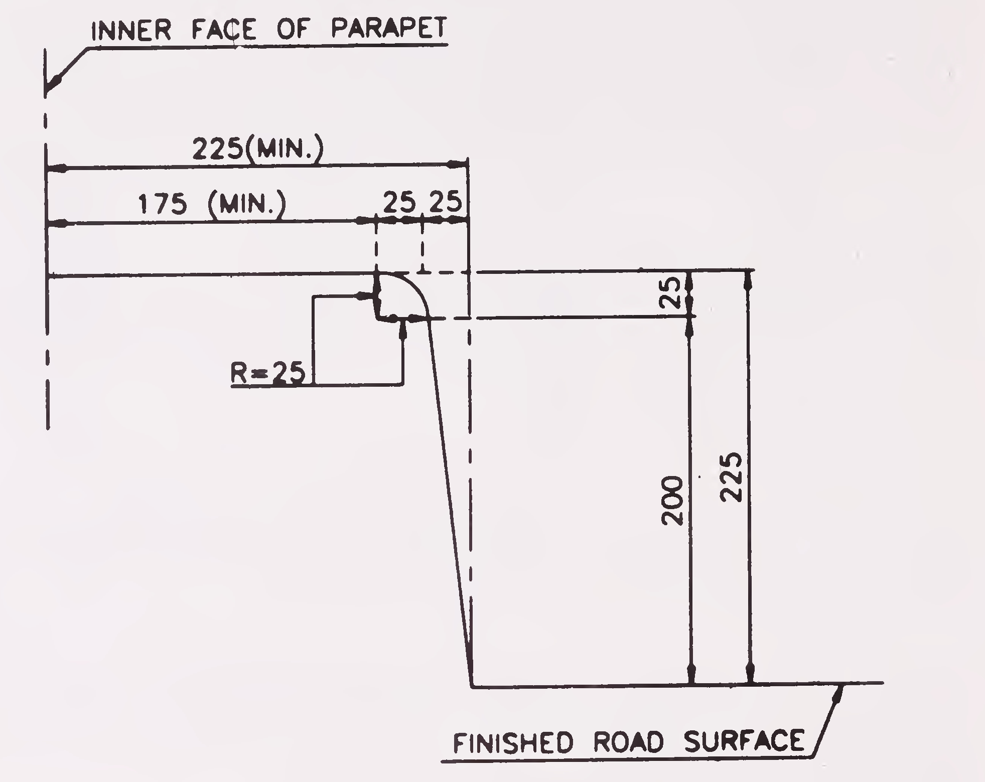
Fig. 2. Outline of Road Kerb (Clause 111.1)
(All Dimensions are in Millimetres)
The section of the kerb should be so designed that it would be safe for vertical and horizontal loads as per relevant Clauses in IRC:6.
A safety kerb will have the same outline as that of a roadway kerb except that the top width shall not be less than 750 mm.
For high level bridges constructed for the use of road traffic only, the width of carriageway shall not be less than 4.25 m for a single lane bridge and 7.5 m for a two-lane bridge and shall be increased by 3.5 m for every additional lane of traffic for a multiple lane bridge. Road bridges shall provide for either one lane, two lanes or multiple of two lanes. Three-lane bridges with two directional traffic shall not be constructed. If a median/central verge is constructed in a wide bridge thus providing two separate carriageways, the carriageway on each side of the verge shall provide for at least two lanes of traffic and width thereof shall individually20
comply with the minimum requirements stipulated above. The width of central/ verge/median, when provided, shall not be less than 1.2 metres.
In addition, cross-sections of 2-lane and multi-lane bridges shall satisfy the following :
For bridges carrying combined road and tramway or any other special type of traffic, the widths indicated in Clause 112.1 shall be modified to suit these special requirements.
Vented causeways/submersible bridges shall provide for at least two lanes of traffic as specified in Clause 112.1 above unless one lane of traffic is specially permitted in the design.
For a bridge on a horizontal curve, the roadway width shall be increased suitably to conform to the requirements stipulated in the relevant IRC Road Standards.21
When a footpath is provided, its width shall not be less than 1.5 metres. For urban and populated areas having large concentration of pedestrian traffic, the width of the footpath shall be suitably increased.
The super elevation on the deck of a bridge on a horizontal curve shall be provided in accordance with the relevant IRC Road Standards.
Due allowance shall be made for the effect of superelevation on the stresses in the various members of the bridge.
If there is a change of gradient on the bridge deck, suitable vertical curve shall be introduced conforming to the stipulations contained in IRC:SP-23.
The minimum horizontal clearance shall be the clear width and the minimum vertical clearance the clear height available for the passage of traffic.
The minimum horizontal and vertical clearances for single lane and multiple lane bridges with vehicular traffic shall be as shown in Fig. 3.
For Road Over Bridges across railway lines, horizontal and vertical clearance shall be governed by the requirements of the Railways as per their specifications.
Unless otherwise specified, bridges shall have all their parts constructed to secure the minimum clearances for traffic given in Fig. 3.
For footways and cycle tracks, a minimum vertical clearance of 2.25 metres shall be provided.
For a bridge constructed on a horizontal curve with superelevated road surface, the horizontal clearance shall be increased on the side of the. inner kerb by an amount equal to 5 metres multiplied by the superelevation. The minimum vertical clearance shall be measured from the superelevated level of the roadway. Extra horizontal clearance required22
for the superelevation will be over and above the increase in width required on a curve under Clause 112.4.
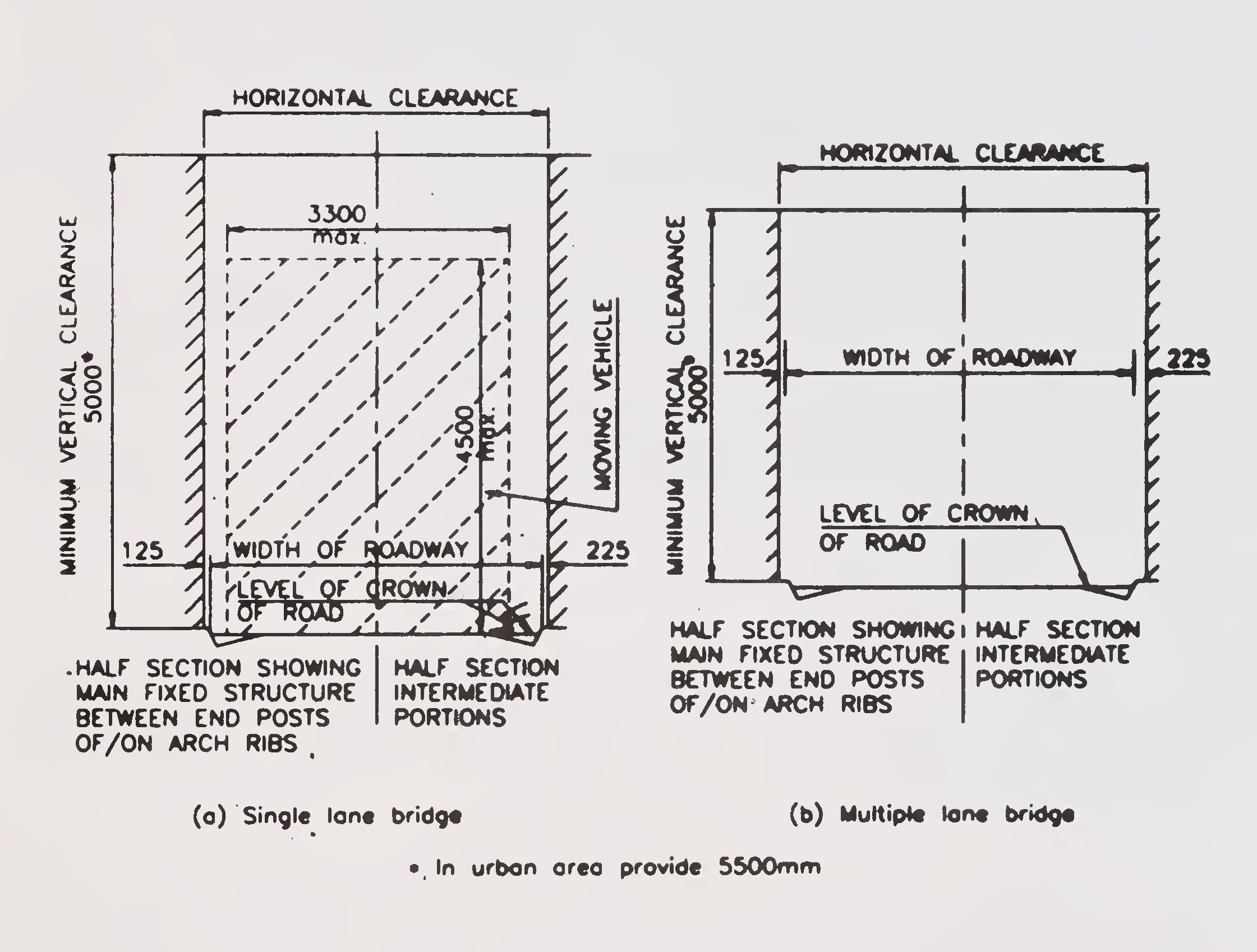
FIG. 3. Clearance Diagram (Clause 114.2)
(All Dimensions are in Millimetres)23
Vertical and lateral clearances at underpasses shall be provided in accordance with the stipulations contained in IRC:54-Lateral and Vertical Clearances at Underpasses for Vehicular Traffic.
Substantial railings or parapets along each side of the bridge shall be provided for the protection of traffic. Consideration shall be given to the architectural features of the railing or parapet to obtain proper proportioning of its various members and its harmony with the structure and the environment as a whole. For bridges situated in severe marine environment, solid wall type parapets along each side of the bridge shall be preferred for better serviceability. Consideration shall be given also to avoid, as far as is consistent with safety and appearance, obstruction of the view from the passing motor cars.
Railings or parapets shall have a minimum height above the adjacent roadway or footway safety kerb surface of 1.1 metres less one half the horizontal width of the top rail or top of the parapet. For bridges exceeding 300 metres in length, the height of railings, determined in the manner stipulated above, shall be increased by 100 mm. The forces to be considered in design shall be as per relevant stipulations of IRC:6. For R.O.Bs across railway lines, these requirements shall be governed by those for railways’ safety.
Where a road provided with cycle tracks goes over a bridge and the cycle track is located immediately next to the bridge railing or parapet, the height of the railing or parapet shall be kept 15 cm higher than that reqired as per Clause 115.1.2 above.
The clear distance between the lower rail and the top of the kerb shall not exceed 150 mm unless the space is filled by vertical or inclined members, the clear distance between which is not more than 150 mm. The strength of the lower rail shall be at least as great as that of the top rail. The space between lower rail and the top rail shall be filled by means of vertical, horizontal or inclined members, the clear distance between which shall be fixed with due regard to the safety of persons and animals using the structure.24
Guard rails shall be provided at the high approaches. The design, layout and materials chosen for the rails shall suitably blend with the surroundings.
Railings shall be either collapsible or removable.
Collapsible railing shall be used where it is necessary to put up the rallings immediately when the bridge is opened to traffic after a submerging flood has receded. Care shall be taken in the structural design of these railings to ensure that they sit well in their grooves and are not liable to be dislodged by floods.
Removable type of railings may be adopted when there is no danger to the traffic using the bridge for short period without railings. Care shall be taken in the structural design of these railings to ensure that the various members are interchangeable and can be easily removed and refitted.
Collapsible or removable railings shall be designed
to resist as far as possible the same forces as specified in Clause 115.1.2 for railings or parapets on high level bridges.
Guide posts/stones may be used in lieu of railings, if the submergence of the road surface over the causeway is so frequent as to render the use of removable or collapsible railings unsatisfactory.
Suitably designed crash barriers shall be provided at the following situations to safeguard against errant vehicles :
For other cases, decision may be taken by the appropriate authority duly considering the importance of the structure and the level of safety warranted.
Crash barriers, when provided, shall be essentially of the following types :
Typical shapes and dimensional details of crash barriers and their locations on the bridge decks with or without footpaths are shown in Fig. 4. These may be suitably modified and augmented depending on the developments in design and future functional requirements in individual cases.
Crash barriers shall be of metal or reinforced concrete and their design shall take into consideration the following factors :
Crash barriers shall provide a smooth and continuous face on the traffic side and shall be suitably extended into the approaches. Exposed rail ends, posts and sharp changes in the geometry of the railings shall be avoided. Suitable reflective (luminous) devices shall be provided on the traffic face of the barrier at intervals to ensure adequate visibility during night and foggy conditions.26
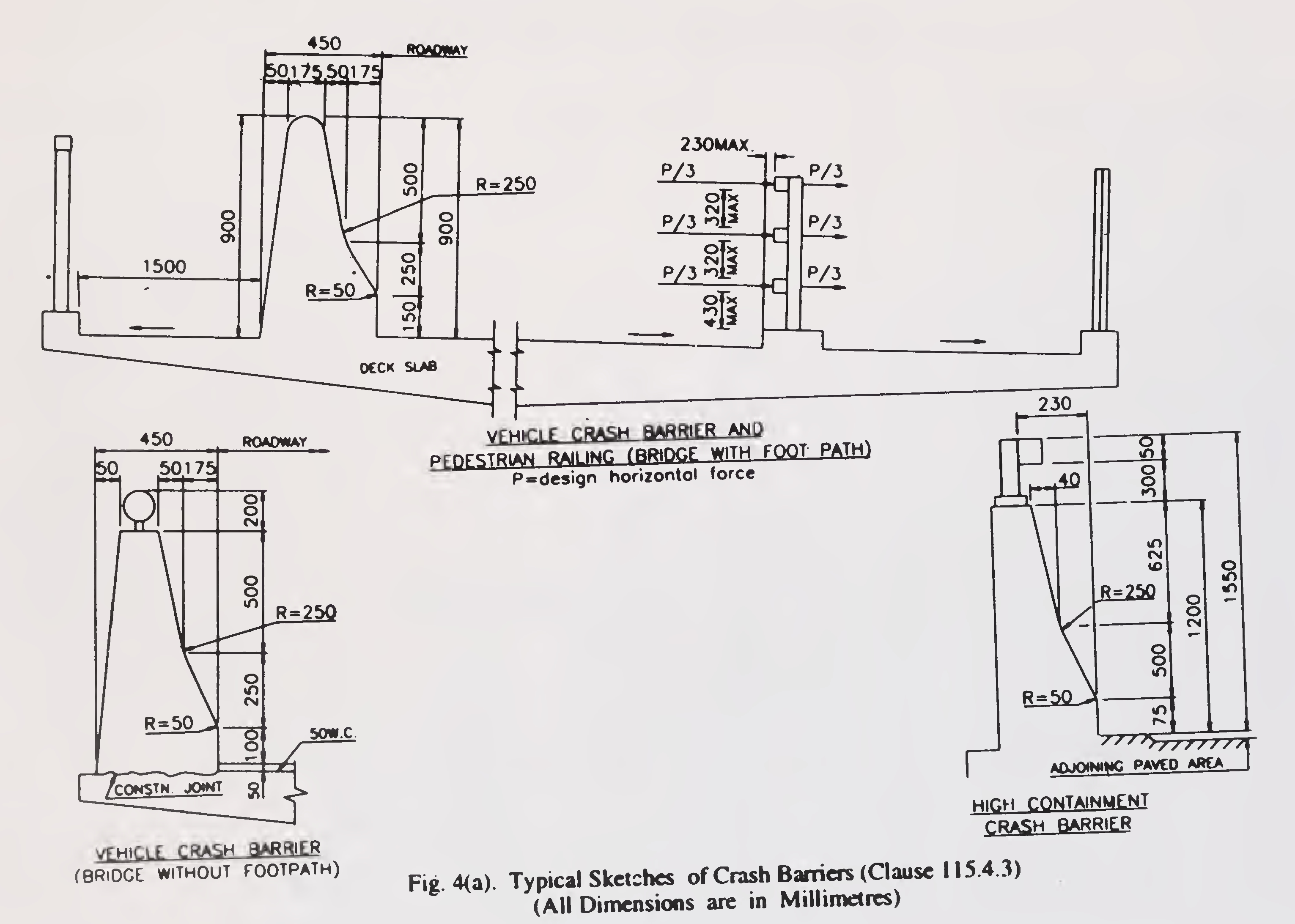
Fig. 4(a). Typical Sketches of Crash Barriers (Clause 115.4.3)
(All Dimensions are in Millimetres)27
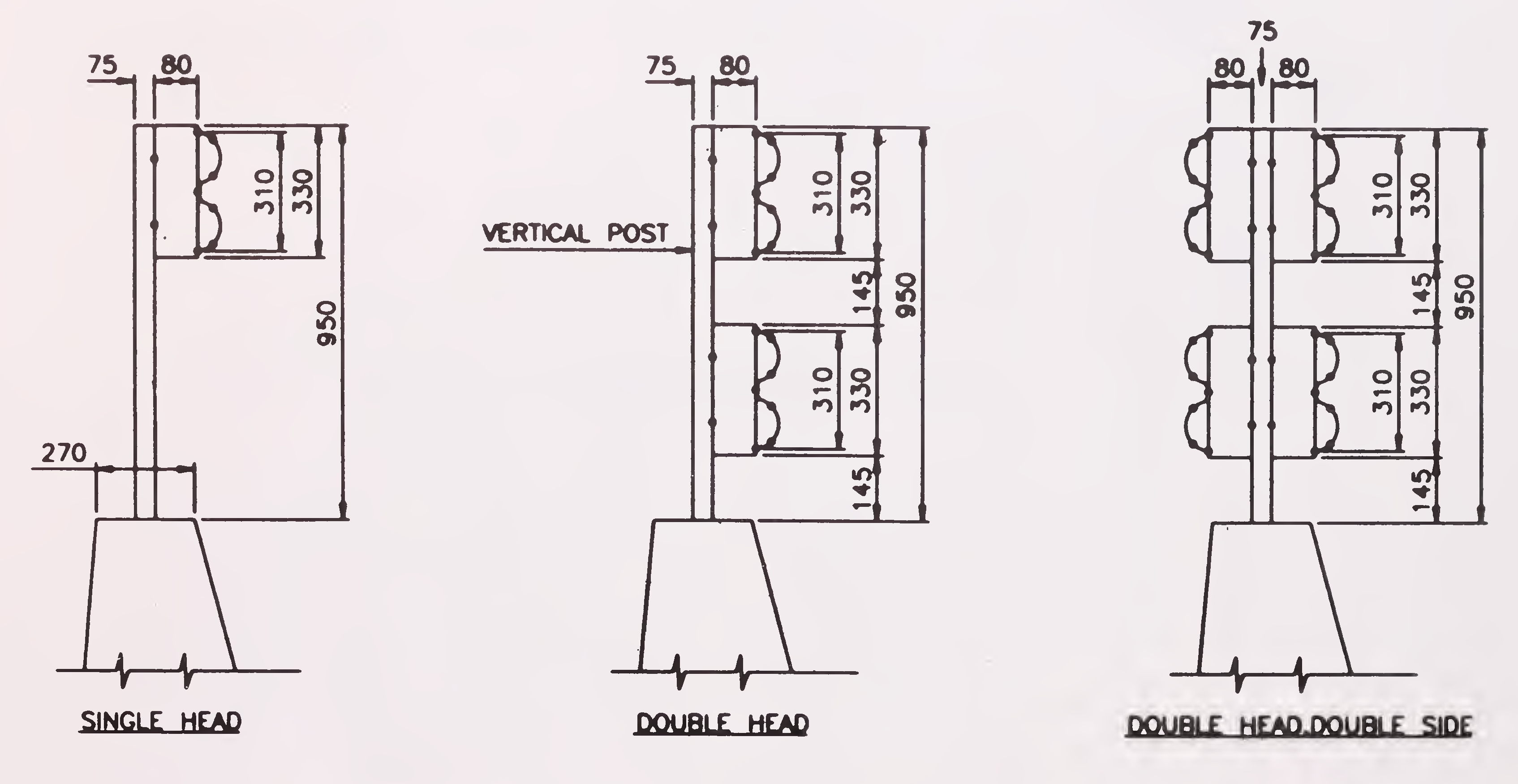
Fig. 4(b). Various Type of Crash Barriers (Clause 115.4.3)
(All Dimensions are in Millimetres)28
The high level bridges may preferably be built in longitudinal gradient with suitably designed cross drains at abutment locations to facilitate proper drainage.
For drainage of a road over bridge/flyover, a suitably designed drainage arrangement should be provided. This may consist of vertical C.I. or rigid PVC pipes connecting the downspouts below the deck with funnels and along the pier upto ground level and eventually joined to the road drainage system. Suitable vertical recess in the piers may be provided to accommodate the drainage pipes rather than providing drip courses underneath the deck slab.
All carriageways and footpath surfaces shall have anti-skid characteristics.
The design of the bridge structure shall be such as to provide for adequate access to all parts of the bridge to facilitate future inspection and maintenance operations.
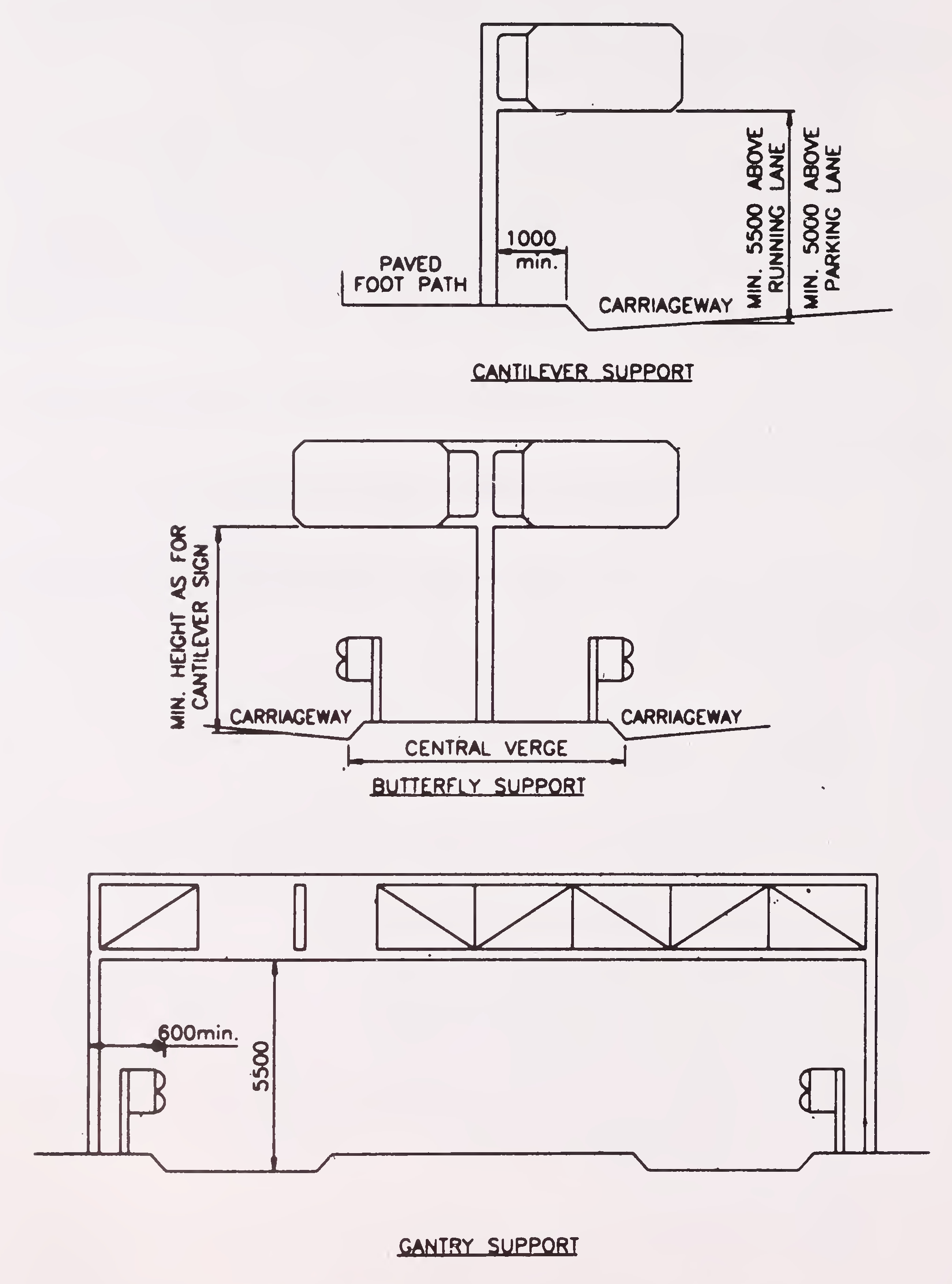
Fig. 5 Typical Arrangement of Supports for Overhead Structures
(CLause 118.1 (iii)
(All Dimensions are in Millimetres)30
The minimum vertical clearance above the roadway in any traffic lane upto the lowest point of the sign or any part of the signage structure or to lamps mounted below the sign shall be 5.5 m. In case of signages mounted over footway, shoulder or parking lane, the vertical clearance may be reduced to 5 m.
The sign supports should be placed at a minimum 1.0 m clear distance behind the traffic face of the roadway kerbs. In longitudinal direction, it shall be placed at a minimum distance of 6 metre from the beginning of a traffic island in any high speed approach direction. On high speed roads, the support shall either be at 9 metre minimum clear distance from the edge of carriageway or adequately protected by ground fence and located at a minimum 0.6 metre clear distance behind the guard rail or parapet/crash barrier.
Where required, provision shall be made for traction wire supports, poles or pillars for lights, trenches or other suitable places for the installation of electric or telephone conduits, water or gas pipes and other similar utilities or services with due care for durability and serviceability of the bridge and its approaches.
The approaches on either side of a straight bridge shall have a minimum straight length of 15 metres and shall be suitably increased where necessary to provide for the minimum sight distance for the design speed. Minimum surfaced width of these straight lengths of approaches shall be equal to the carriageway width on the bridge.
Note: In difficult situations, the Engineer responsible for the design may at his discretion permit a reduction in the minimum straight length of approaches, provided reasons for making a departure from the Code are clearly recorded.
Where horizontal curves have to be provided on the approaches beyond the straight portion on either side, the minimum radius of curvature, the super elevation and transition length for various speed and the curve radii shall be provided in accordance with relevant stipulations contained in IRC:38.31
If the approach is in filling, borrowpits should not be dug close to the embankment to avoid risk of parallel flow being developed which may endanger safety of the embankment. Suitable minimum distance from the toe of embankment and depth of borrow pits for the immediate approaches of the bridge may be specified for each case, depending on the size of the channel and topographical conditions of the area. In this connection, provision made in IRC: 10 "Recommended Practice for Borrowpits for Road Embankments Constructed by Manual Operation" may also be kept in view.
If there is a change of gradient, suitable vertical curves shall be introduced conforming to relevant stipulations contained in IRC:23. A single vertical curve shall be provided for bridges having a total length upto 30 m.
Approaches to submersible bridges/vented causeways likely to be affected by floods shall be provided with suitably designed protective works.
Bearings for the bridges shall be designed for all movements and rotations as applicable and conform to the provision contained in IRC:83 Parts I & II.
To cater for expansion and contraction movements, suitably designed expansion joints shall be provided at the expansion ends of all spans and at other points where they may be necessary alongwith appropriate drainage arrangement. The number of such expansion joints shall be kept minimum, as far as practicable. Care shall be taken to ensure watertightness of the expansion joints.
The foundations for piers and abutments shall be at such depths that they are safe against scour and large impacts where necessary and are protected against it. They shall be taken down to a level sufficient to secure firm foundation from consideration of bearing capacity, overall stability and suitability of the strata at the founding level and upto sufficient depth below it. The foundations shall be designed in accordance with the provisions made in IRC:78.32
Illumination for bridges, grade separators and interchanges shall be decided by the appropriate authority and conform to the following requirements :
The installation, lighting arrangement, method of control, switches etc. shall all conform to the provision contained in IS: 1944.
At highway interchanges, different lighting arrangements viz. low masts or high masts or combination of both may be considered and the one which gives optimum results from the view points of aesthetics, safety, illumination and ease of maintenance may be adopted. Light colour distinction at junctions to give an early warning signal to approaching vehicles may also be considered.
Illumination levels for the vehicular and pedestrian subways/underpasses may be kept same as those on the approaches at either end of the subway/underpass.
Visual forms of bridges, viaducts or flyover structures etc. should be selected with care to be in harmony with the general landscape with a33
view to maintaining the aesthetics of the surrounding. While planning such structures, the following general requirements may be kept in view :
APPENDIX-1
Clause 103.1.4
UNIT HYDROGRAPH METHOD
The Unit Hydrograph, frequently termed as the unit graph, is defined as the hydrograph of storm run-off at a given point in a river, resulting from an isolated rainfall of unit duration occuring uniformly over the catchment, and producing a unit run-off. The unit run-off adopted is 1 cm depth over a catchment area.
The term "Unit-Rainfall Duration" is the duration of rainfall excess resulting in the unit hydrograph. Usually, unit hydrographs are derived for specified unit durations, say, 6 hours, 12 hours. etc., and derived unit hydrographs for durations other than these are converted into unit hydrographs of the above unit durations. The duration selected should not exceed the period during which the storm is assumed to be approximately uniform in intensity over various parts of the catchment. A 6 hours unit duration is suitable and convenient for studies relating to catchments larger than 250 sq.km.
The unit hydrograph represents the integrated effects of all the basin constants, viz., drainage area, shape, stream pattern channel capacities, stream and land slopes.
The derivation and application of the unit hydrograph is based on the following principles :
Three methods are generally available for giving unit hydrographs at any point in a river.
The determination of design flood, after the unit hydrograph has been derived, involves the following steps :
A rational determination of critical design storm for a catchment requires a comprehensive study of major storms recorded in the region and an evaluation of effects of local conditions upon rainfall rate. This is particularly necessary in the case of design storms covering a large area of several thousand square kms.
In the case of areas less than a few thousand square kms, certain assumptions can be made regarding rainfall patterns and intensity variations without being inconsistent with meteorological causes. They simplify design-storm estimation, but would entail high degree of conservation.36
APPENDIX 1(a)
Clause 103.1.4
REPORTS BROUGHT OUT BY CENTRAL WATER COMMISSION
UNDER LONG TERM PLAN
| Sl. No. |
Name of Sub-zone | Sub-zone No. |
|---|---|---|
| 1. | Chambal sub-zone | 1(b) |
| 2. | Betwa sub-zone | 1(c) |
| 3. | Sone sub-zone | 1(d) |
| 4. | Upper Indo-Ganga Plains sub-zone | 1(e) |
| 5. | Middle Ganga Plains sub-zone | 1(0 |
| 6. | Lower Gangetic Plains sub-zone | 1(g) |
| 7. | North Brahmaputra basin sub-zone | 2(a) |
| 8. | South Brahmaputra basin sub-zone | 2(b) |
| 9. | Mahi and Sabarmati sub-zone | 3(a) |
| 10. | Lower Narmada and Tapi sub-zone | 3(b) |
| 11. | Upper Narmada and Tapi sub-zone | 3(c) |
| 12. | Mahanadi sub-zone | 3(d) |
| 13. | Upper Godavari sub-zone | 3(e) |
| 14. | Lower Godavari sub-zone | 3(0 |
| 15. | Krishna & Pannar sub-zone | 3(h) |
| 16. | Kaveri river sub-zone | 3(i) |
| 17. | Eastern Coast sub-zones | 4(a), 4(b) & 4(c) |
| 18. | ||
| 19. | ||
| 20. | West Coast region sub-zones | 5(a) & 5(b) |
| 21.37 |
APPENDIX-2
Clause 110.1.3
TYPICAL METHOD OF DETERMINATION OF WEIGHTED MEAN DIAMETER OF PARTICLES (dm)
Representative disturbed samples of bed materials shall be taken at every change of strata upto the maximum anticipated scour depth. The sampling should start from 300 mm below the existing bed. About 500 gms of each of the representative samples so collected shall be seived by a set of standard seives and the weight of soil retained in each seive is taken. The results thereof are then tabulated. A typical test result is shown below (Tables I & II)
| Seive Designation | Sieve Opening (mm) |
Weight of Soil retained (gm) |
Per cent retained |
|---|---|---|---|
| 5.60 mm | 5.60 | 0 | 0 |
| 4.00 mm | 4.00 | 0 | 0 |
| 2.80 mm | 2.80 | 16.90 | 4.03 |
| 1.00 mm | 1.00 | 76.50 | 18.24 |
| 425 micron | 0.425 | 79.20 | 18.88 |
| 180 micron | 0.180 | 150.40 | 35.86 |
| 75 micron | 0.75 | 41.00 | 9.78 |
| Pan | - | 55.40 | 13.21 |
| Total : | 419.40 | ||
| Sieve No. | Average size (mm) | Percentage of weight retained | Column (2) x column (3) |
|---|---|---|---|
| (1) | (2) | (3) | (4) |
| 4.00 to 2.80 mm | 3.40 | 4.03 | 13.70 |
| 2 80 to 1.00 mm | 1.90 | 18.24 | 34.66 |
| 1.00 to 425 micron | 0.712 | 18.88 | 13.44 |
| 425 to 180 micron | 0.302 | 35.86 | 10.83 |
| 180 to 75 micron | 0.127 | 9.78 | 1.24 |
| 75 micron & below | 0.0375 | 13.21 | 0.495 |
| 74.365 | |||
| |||