
In order to promote public education and public safety, equal justice for all, a better informed citizenry, the rule of law, world trade and world peace, this legal document is hereby made available on a noncommercial basis, as it is the right of all humans to know and speak the laws that govern them.
EAS 223:2001
ICS 59.080.30
HS 9607.11.10(metal)
HS 9607.19.10(other)
EAST AFRICAN COMMUNITY
© EAC 2001
First Edition 2001
iDevelopment of the East African Standards has been necessitated by the need for harmonizing requirements governing quality of products and services in East Africa. It is envisaged that through harmonized standardization, trade barriers which are encountered when goods and services are exchanged within the Community will be removed.
In order to achieve this objective, the Partner States in the Community through their National Bureaux of Standards, have established an East African Standards Committee.
The Committee is composed of representatives of the National Standards Bodies in Partner States, together with the representatives from the private sectors and consumer organizations. Draft East African Standards are circulated to stakeholders through the National Standards Bodies in the Partner States. The comments received are discussed and incorporated before finalization of standards, in accordance with the procedures of the Community.
East African Standards are subject to review, to keep pace with technological advances. Users of the East African Standards are therefore expected to ensure that they always have the latest versions of the standards they are implementing.
© East African Community 2001 — All rights reserved*
East African Community
P O Box 1096
Arusha
Tanzania
Tel: 255 27 2504253/8
Fax: 255-27-2504481/2504255
E-Mail: eac@eachq.org
Web: www.each.int
* © 2001 EAC — All rights of exploitation in any form and by any means reserved worldwide for EAC Partner States’ NSBs.
ii| 1 | Scope | 1 |
| 2 | Application | 1 |
| 3 | Definitions | 1 |
| 4 | Requirements | 1 |
| 5 | Marking | 2 |
| 6 | Packing | 2 |
| Annex A Guidance factors | 4 | |
| Annex B Conditioning and testing atmosphere | 4 | |
| Annex C Puller attachment | 5 | |
| Annex D Closed-end test | 6 | |
| Annex E Top-stop test | 7 | |
| Annex F Open-end fastener box test | 8 | |
| Annex G Lateral strength test | 9 | |
| Annex H Lateral strength of open-end attachment test | 10 | |
| Annex J Slider locking test | 11 | |
| Normative references | 12 | |
Zippers — Specification
This East African Standard specifies performance requirements for zippers made from interlocking components mounted on textile tapes.
This standard applies to all types of zippers except those designed for aeronautical purposes, those intended to be exposed to corrosive influences and zippers of complicated structure such as three-way and double-pull as used in tents.
For the purpose of this standard, the definition given below and those in EAS 260* shall apply:
a quality of zippers having one design, one performance code and one side
All zippers shall be grouped into five performance codes 1 to 5, 5 being the most stringent as shown in Table 1.
Each zipper shall comply with the respective code performance requirements given in Table 2.
Each test shall be done in accordance with Appendices C to J respectively.
Zippers shall comply with fastness and dimensional change requirements of Table 3.
The textile tape used in making zippers shall be free from any manufacturing and dyeing defects.
The tape shall be enough to withstand the force applied during lateral strength test (Annex G).
The thread used to secure the continuous monofilament to the tape shall comply to EAS 250 [4] Parts 1 and 2.
The fibre composition of the thread shall be the same as that of the tape.
* Standards referred to in this standard are listed at the back.
1The thread shall be strong enough to withstand the force applied to zippers during ‘Lateral Strength Test’ (Annex G).
The length of zippers shall be as declared, subject to a tolerance of 1.5 per cent or +3 mm, whichever is greater.
All parts and materials used in making zippers shall conform to the guidance factor as given in Annex A.
Each zipper shall be permanently marked with the following information:
A batch or several batches of zippers shall have the following information which shall be indicated on the package, the swing ticket or accompanying documents:
Zippers shall be properly packed in a carton (box) or any suitable container to avoid any entanglement during transit and/or unpacking.
| Performance code | 1 (ultra-light) |
2 (Light) |
3 (Medium) |
4 (Medium-heavy) |
5 (Heavy) |
|---|---|---|---|---|---|
| End Use | |||||
| Dresses | |||||
| Knitwear | |||||
| Light leather gods | |||||
| Skirts, jeans or trousers | |||||
| Upholstery | |||||
| Foundation garments | |||||
| Coats and jackets | |||||
| Overalls | |||||
| Luggage | |||||
| Slippers | |||||
| Sleeping bags | |||||
| Lightweight and inner tents | |||||
| Footwear | |||||
| Leather garments | |||||
| Ski clothes | |||||
| Wet suits | |||||
| Awnings and frame tents |
| Test description | Performance code | Method of test | ||||
|---|---|---|---|---|---|---|
| 1 | 2 | 3 | 4 | 5 | ||
| Puller attachment, N (Min.) | 70 | 80 | 200 | 250 | 300 | Annex C |
| Closed end test, N (Min.) | 35 | 60 | 80 | 100 | 140 | Annex D |
| Top stop test, N (Min.) | 50 | 70 | 90 | 110 | 130 | Annex E |
| Open end fastener box test, N (Min.) 40 | 40 | 70 | 90 | 120 | 150 | Annex F |
| Lateral strength test, N (Min.) | 150 | 200 | 250 | 370 | 470 | Annex G |
| Lateral strength of open end, N. (Min.) | 40 | 70 | 90 | 120 | 160 | Annex H |
| Slider locking test N (Min.) | 10 | 15 | 25 | 40 | 60 | Annex J |
| Characteristic | Performance level | Method of test |
|---|---|---|
| Colour fastness to: | Change in shade and staining: 4 or better | EAS 237 [2] method 1 and 3 |
| (a) Washing | ||
| (b) Dry cleaning | Changing in shade and staining: 4 or better | EAS 236 [3] |
| Dimensional change (Max.) | Warpway and Weftway: ± 3 per cent | EAS 237 [2] method 3 |
| (a) After 3 washings | ||
| (b) After 3 dry -cleanings | Warpway and Weftway: ±2 per cent. | EAS 236 [3] |
The following shall be taken into consideration when specifying zippers.
Zippers shall be conditioned and tested in the standard atmosphere for testing textiles as defined in EAS 240.
4The puller is subjected to tension while the slider is rigidly supported.
The testing machine of the constant-rate-of traverse type and the opening speed of the jaws at 100 ± 15 mm/min. The load range should be such that the breaking strength of the test specimen falls between 15 per cent and 90 per cent of the maximum on the scale. A marking device for the slide, such as face-plate or a blanking-off plate, is required so that tension is confined to the puller and its attachment to the slider (Figure 1).
Mount the specimen in one gripping device of the testing machine with the puller through a hole in the mask. Arrange the mask so that the slider and the chain are rigidly clamped in place only the puller being free. Secure the end of the puller to the other gripping device so that the tension is applied at 900 to the face of the slider. Set the testing machine in operation until the specified loading is reached, unless the specimen fails earlier.
Record the test results in accordance with 4.2.1.
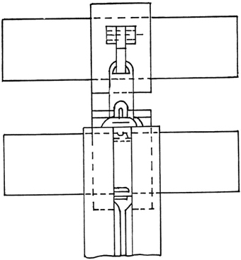
Figure 1 — Puller attachment test
5The bottom stop is subjected to a force via the slider by tension applied to the stringers.
The testing machine as described in Annex C is used. Mounting of the specimen is as shown in Figure 2.
The test specimen is in the open position, the slider being adjacent to bottom stop. Ensure that the locking mechanism is released. Grip the stringer in the two jaws approximately 10 cm away from the slider. (This may be achieved by cutting away the surplus stringer). Apply a longitudinal force to the stringers thus loading the slider against the bottom stop. Set the machine in operation until the specified loading is reached, unless the specimen fails earlier.
Report as in C.4.
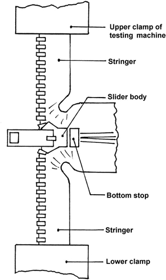
Figure 2 — Closed-end test
6The top-stop is subjected to a force via the slider applied through the puller.
The testing machine as described in Annex C is used. Mount the specimen as shown in Figure 3.
The test specimen is in the closed position with the slider adjacent to the top. Secure the puller in one jaw of the machine and the other end of the specimen in the other jaw, steps being taken to avoid damaging the chain. Set the machine in operation until the specified force is reached unless the specimen fails earlier.
Report as in C.4.
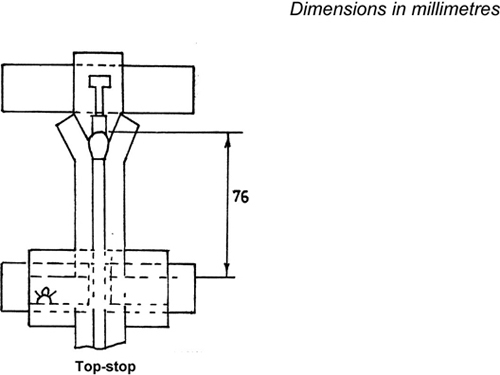
Figure 3 — Top-stop test
7The box is subjected to a longitudinal force while the chain is in the closed position.
The testing machine described in Annex C is used. Mount the specimen as shown in Figure 4.
With the test specimen in closed position, clamp the interlocked chain into the jaw of the testing machine, steps being taken to avoid damaging the chain. Clamp a slotted plate, shaped to clear the tape, chain and pin and to bear against the whole of the top edges of the box, into the other jaw. Set the machine in operation until the specified force is reached, unless the specimen fails earlier.
Report as in C4.
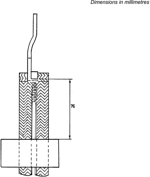
Figure 4 — Open-end fastener box test
8The test specimen is subjected to lateral force under controlled conditions while the fastener chain is in the closed position.
The testing machine as described in Annex C is used. The gripping surface 25.4 mm wide are used. The jaws shall be so constructed and finished so as not to damage the tape, and not to allow slippage of the specimen. (See Figure 5).
Secure the test specimen in place with the gripping devices so arranged that at least the width of each tape is gripped and there is at least 25.4 mm of closed chain on each side. Set the machine in operation until the specified force is reached, unless the specimen fails earlier.
Report as in C.4.
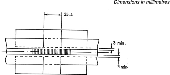
Figure 5 — Lateral strength test
9The test specimen is subjected to straight lateral loading under controlled conditions while the fastener chain is in closed position.
The testing machine as described in Annex C is used. The gripping jaws shall be 6 mm wide for testing zippers for performance codes 1 and 2, and 12 mm for codes 3, 4 and 5. The jaws shall be so constructed and finished as not to damage the tape or allow slippage during the test, (See Figure 6).
Secure the test specimen in place with the gripping jaws set approximately 3 mm from the sides of the box, and with one edge of each jaw aligned with the ends of tapes. Set the machine in operation until the specified load is reached, unless the specimen fails earlier.
Report as in C.4.
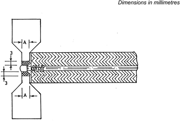
Figure 6 — Lateral strength of open-end attachment
10The slider is locked on the chain and the locking device subjected to tension, the load being applied at 180o to the device, via the chain stringers in such a way as to bring the locking device under pressure from the chain.
The test machine as described in Annex B is used. Mounting of the specimen is as shown in Figure 7.
The test specimen is in the open position with the locking device locked into the chain 25 mm from the top-stops. Set the jaws 50 mm apart and secure the top of the stringer into the jaws adjacent to the top so that the top of the slider is 25 mm from the edge of each jaw. Set the machine in motion and increase the load until the locking mechanism slips or the specimen fails.
Report as in C.4.
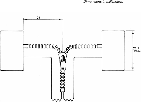
Figure 7 — Slider locking test
11