
In order to promote public education and public safety, equal justice for all, a better informed citizenry, the rule of law, world trade and world peace, this legal document is hereby made available on a noncommercial basis, as it is the right of all humans to know and speak the laws that govern them.
EAS 177: 2011
ICS 75.160.20
© EAS 2011
Second Edition 2011
i|
Copyright notice This EAC document is copyright-protected by EAC. While the reproduction of this document by participants in the EAC standards development process is permitted without prior permission from EAC, neither this document nor any extract from it may be reproduced, stored or transmitted in any form for any other purpose without prior written permission from EAC. Requests for permission to reproduce this document for the purpose of selling it should be addressed as shown below or to EAC’s member body in the country of the requester:
Reproduction for sales purposes may be subject to royalty payments or a licensing agreement. Violators may be persecuted |
| Page | ||||
| Foreword | iv | |||
| 1 | Scope | 1 | ||
| 2 | Normative references | 1 | ||
| 3 | Terms and definitions | 2 | ||
| 4 | Requirements | 3 | ||
| 4.1 | General | 3 | ||
| 4.1.1 | Approved dyes and markers | 3 | ||
| 4.1.2 | Approved additives | 3 | ||
| 4.1.3 | Fatty Acid Methyl Ester (FAME) | 3 | ||
| 4.1.4 | Cloud point | 3 | ||
| 4.2 | Specific quality requirements | 3 | ||
| 4.3 | Precision and dispute | 5 | ||
| 5 | Pump labelling | 5 | ||
| 6 | Adulteration | 5 | ||
| Annex A (normative) Sampling | 6 | |||
| A.1 | General | 6 | ||
| A.2 | Sampling from retail site pumps and commercial site fuel dispensers | 6 | ||
| A.3 | Sample containers and closures | 6 | ||
| A.3.1 | Containers | 6 | ||
| A.3.2 | Closures | 6 | ||
| A.3.4 | Safety requirements | 6 | ||
| A.3.5 | Sampling procedure | 7 | ||
| A.4 | Sampling statement | 8 | ||
| Annex B (informative) Nozzle extensions for sampling automotive gas oil and their use | 12 | |||
| B.1 | General | 12 | ||
| B.2 | Extension pieces | 12 | ||
| B.3 | Procedure | 12 | ||
Development of the East African Standards has been necessitated by the need for harmonizing requirements governing quality of products and services in the East African Community. It is envisaged that through harmonized standardization, trade barriers that are encountered when goods and services are exchanged within the Community will be removed.
In order to achieve this objective, the Community established an East African Standards Committee mandated to develop and issue East African Standards.
The Committee is composed of representatives of the National Standards Bodies in Partner States, together with the representatives from the private sectors and consumer organizations. Draft East African Standards are circulated to stakeholders through the National Standards Bodies in the Partner States. The comments received are discussed and incorporated before finalization of standards, in accordance with the procedures of the Community.
East African Standards are subject to review, to keep pace with technological advances. Users of the East African Standards are therefore expected to ensure that they always have the latest versions of the standards they are implementing.
DEAS 158 was prepared by Technical Committee EAS/TC 000, TC title, Subcommittee SC 0, SC title.
This second edition cancels and replaces the first edition (EAS 177:2000), which has been technically revised.
ivAutomotive diesel — Specification
This East African Standard specifies the requirements and methods of test for automotive gas oil (AGO).
This standard applies to diesel used for automotive diesel engines, as in heavy commercial vehicles, diesel engine vehicles and tractors. It does not cover diesel fuel used in industrial burners or stationary diesel engines.
The following referenced documents are indispensable for the application of this document. For dated references, only the edition cited applies. For undated references, the latest edition of the referenced document (including any amendments) applies.
ASTM D2500 [IP 309], Standard test method for cloud point of petroleum products
EN 12662, Liquid petroleum products — Determination of contamination in middle distillates
EN 12916, Petroleum products — Determination of aromatic hydrocarbon types in middle distillates — High performance liquid chromatography method with refractive index detection
EN 14078, Liquid petroleum products — Determination of fatty acid methyl ester (FAME) content in middle distillates — Infrared spectrometry method
EN 14214, Automotive fuels — Fatty acid methyl esters (FAME) for diesel engines — Requirements and test methods
EN 14274 [IP 508], Methods of test for petroleum and its products — Automotive fuels — Assessment of petrol and diesel quality — Fuel quality monitoring system (FQMS)
EN 14331, Liquid petroleum products Separation and characterisation of fatty acid methyl esters (FAME) from middle distillates Liquid chromatography (LC)/gas chromatography (GC) method
ISO 2049, Petroleum products — Determination of colour (ASTM scale)
ISO 2160, Petroleum products — Corrosiveness to copper — Copper strip test
ISO 2719, Determination of flash point — Pensky-Martens closed cup method
ISO 3015, Petroleum products — Determination of cloud point
ISO 3104, Petroleum products — Transparent and opaque liquids — Determination of kinematic viscosity and calculation of dynamic viscosity
ISO 3170, Petroleum liquids — Manual sampling
ISO 3171, Petroleum liquids — Automatic pipeline sampling
1ISO 3675, Crude petroleum and liquid petroleum products — Laboratory determination of density — Hydrometer method
ISO 3733, Petroleum products and bituminous materials — Determination of water — Distillation method
ISO 3735, Crude petroleum and fuel oils — Determination of sediment — Extraction method
ISO 4259, Petroleum products — Determination and application of precision data in relation to methods of test ISO 4264, Petroleum products — Distillate fuels — Calculation of cetane index
ISO 5165, Petroleum products — Determination of the ignition quality of diesel fuels — Cetane engine method
ISO 6245, Petroleum products — Determination of ash
ISO 6615, Petroleum products — Determination of carbon residue — Conradson method
ISO 6619, Petroleum products and lubricants — Neutralization number — Potentiometric titration method
ISO 7537, Petroleum products — Determination of acid number — Semi-micro colour-indicator titration method
ISO 10370, Petroleum products — Determination of carbon residue (micro method)
ISO 12156-1, Diesel fuels — Assessment of lubricity by HFRR
ISO 12185, Crude petroleum and petroleum products — Determination of density — Oscillating U-tube method
ISO 12205, Petroleum products — Determination of the oxidation stability of distillate fuels
ISO 12937, Petroleum products — Determination of water — Coulometric Karl Fisher titration method
ISO 13759, Petroleum products — Determination of alkyl nitrate in diesel fuels — Spectrometric method
ISO 20846, Petroleum products — Determination of sulfur content of automotive fuels — Ultraviolet fluorescence method
ISO 20847, Petroleum products — Determination of sulfur content of automotive fuels — Energy dispersive X-ray fluorescence spectrometry
ISO 20884, Petroleum products — Determination of sulfur content of automotive fuels — Wavelength-dispersive X-ray fluorescence spectrometry
US ISO 17020, General criteria for the operation of various types of bodies performing inspection
US ISO 3405, Petroleum products — Determination of distillation characteristics at atmospheric pressure
For the purposes of this standard, the following terms and definitions shall apply.
gas-oil that has been specially formulated for use in medium and high-speed diesel engines, mostly used in the transportation market
2empty capacity left in a fixed volume sample receiver/container above the liquid surface
The use of dyes or markers is allowed. It should however be noted that these are as approved by the authority responsible for fuels in the country and that they shall serve the purpose for which they are intended and, shall not deter any parameters of diesel out of the specified ranges as indicated under Table 1.
In order to improve the performance quality, the use of additives is allowed. Suitable fuel additives without known harmful side-effects are recommended in the appropriate amount, to help avoid deterioration of driveability and emissions control durability. Other technical means with equivalent effect may also be used.
Diesel fuel may contain up to 5 % (V/V) of FAME complying with EN 14214.
NOTE A suitable method for the separation and identification of FAME is given in EN 14331.
Cloud point shall be reported in accordance with ISO 3015.
When tested by the methods indicated in Table 1, automotive diesel fuel shall be in accordance with the limits specified in Table 1.
3| Property | Unit | Limits | Test method a) | |
|---|---|---|---|---|
| Minimum | Maximum | |||
| Cetane number b) | 51.0 | — | ISO 5165 | |
| Cetane index | 48.0 | — | ISO 4264 | |
| Density at 15 °C c) | kg/m3 | 820 | 870 | ISO 3675 ISO 12185 |
| ASTM colour | — | 3.5 | ISO 2049 | |
| Polycyclic aromatic hydrocarbons d), e) | % (m/m) | — | 11 | EN 12916 |
| Sulfur content f) | mg/kg | — | 500 | ISO 20846; |
| ISO 20847 | ||||
| Flash point | °C | Above 55 | — | ISO 2719 |
| Carbon residue g) (on 10 % distillation residue) | % (m/m) | — | 0.2 | ISO 10370 ISO 6615 |
| Ash content | % (m/m) | — | 0.01 | ISO 6245 |
| Water content | mg/kg | — | 200 | ISO 12937 |
| Copper strip corrosion (3 h at 50 °C) | rating | Class 1 | ISO 2160 | |
| Oxidation stability | g/m3 | — | 25 | ISO 12205 |
| Lubricity, corrected wear scar diameter (wsd 1.4) at 60 °C | μm | — | 460 | ISO 12156-1 |
| Viscosity at 40 °C | mm2/s | 1.60 | 5.50 | ISO 3104 |
| Cold filter plugging point (CFPP) | °C, max | — | 12 | ASTM D2500 [IP 309] |
| Sediment | % m/m | — | 0.01 | ISO 3735 |
| Neutralization value: | ||||
| Strong acid No., KOH | mg/g | Nil | ISO 6619 | |
| Total acid No., KOH | mg/g | 0.5 | ||
| Distillation h) Distillation at 10°C Distillation at 50°C Distillation at 90°C |
200 260 320 |
242 290 350 |
US ISO 3405 | |
| % (V/V) recovered at 250 °C | % (V/V) | <65 | ||
| % (V/V) recovered at 350 °C | % (V/V) | 85 | ||
| 95 % (V/V) recovered at Final Boiling point |
°C °C |
350 |
360 385 |
|
| Fatty acid methyl ester (FAME) content j) | % (V/V) | — | 5 | ISO En 14214 |
| Initial boiling point | 160 | 190 | 4 | |
|
a) See also 4.3.1 b) See also 4.3.4 c) See also 4.3.2 d) For the purposes of this East African Standard, polycyclic aromatic hydrocarbons are defined as the total aromatic hydrocarbon content less the mono-aromatic hydrocarbon content, both as determined by EN 12916. e) EN 12916 is not able to distinguish between polycyclic aromatic hydrocarbons and fatty acid methyl esters (FAME). FAME, if present in diesel fuels, will overestimate the value for polycyclic aromatic hydrocarbons. f) See also 4.3.3 g) See also note below table h) For the calculation of the cetane index the 10 %, 50 % and 90 % (V/V) recovery points are also needed. j) FAME shall meet the requirements of EN 14214. NOTE The limiting value for the carbon residue given in Table 1 is based on product prior to addition of ignition improver, if used. If a value exceeding the limit is obtained on finished fuel in the market, ISO 13759 shall be used as an indicator of the presence of a nitrate-containing compound. If an ignition improver is thus proved present, the limit value for the carbon residue of the product under test cannot be applied. The use of additives does not exempt the manufacturer from meeting the requirement of maximum 0.30 % (m/m) of carbon residue prior to addition of additives. |
||||
All test methods referred to in this East African Standard include a precision statement. In cases of dispute, the procedures for resolving the dispute and interpretation of the results based on test method precision, described in ISO 4259, shall be used.
In cases of dispute concerning density, ISO 3675 shall be used.
In cases of dispute concerning sulfur content, ISO 20847 is unsuitable as an arbitration method.
For the determination of cetane number alternative methods may also be used in cases of dispute, provided that these methods originate from a recognized method series, and have a valid precision statement, derived in accordance with ISO 4259, which demonstrates precision at least equal to that of the referenced method. The test result, when using an alternative method, shall also have a demonstrable relationship to the result obtained when using the referenced method.
Information to belabelled on dispensing pumps used for delivering automotive diesel fuel, and the dimensions of the mark shall be in accordance with the requirements of legal metrology regulations for the marking of pumps for automotive diesel fuel.
The product shall be not contaminated with other petroleum products such as kerosene and petrol.
5(normative)
Samples shall be taken as described in ISO 3170 or ISO 3171 and/or in accordance with the requirements of legal regulations for the sampling of automotive diesel fuel.
In view of the sensitivity of some of the test methods referred to in this East African Standard, particular attention shall be paid to compliance with any guidance on sampling containers which is included in the test method standard.
This clause specifies a procedure for drawing, from fuel dispensers, samples of diesel fuel to be used for the assessment of automotive fuel quality in accordance with EN 14274. This standard does not cover the sampling of Liquefied Petroleum Gas (LPG).
WARNING: The use of this standard may involve hazardous materials, operations and equipment. This standard does not purport to address all of the safety problems associated with its use. It is the responsibility of the user of this standard to establish appropriate safety and health practices and determine the applicability of regulatory limitations prior to use.
These shall be unused metallic containers of approximately one-litre capacity, constructed from lead-free material, with packing glands or welded joints, able to withstand normal internal pressures encountered during normal operations. The containers shall be equipped with an external fitting to enable them to be sealed. The container shall not have been treated with a petroleum-based rust-preventative.
NOTE Lead solder may be used for the attachment of external fittings.
These shall be able to retain the integrity of the sample. Insert disks may additionally be used to close the container outlet. Suitable closures include screw caps fitted with a washer resistant to the product being sampled. Cork or rubber washers shall not be used.
The following minimum safety requirements shall be read in conjunction with the requirements for safety as given in ISO 3170 and, in addition, any national or local safety, environmental and transportation regulations.
Personnel drawing the samples shall be made aware of the potential hazards and be given instructions in safety precautions to be observed.
6Care shall be taken to avoid breathing petroleum vapours during the sampling. Protective gloves of hydrocarbon-insoluble materials, eye, mouth and nose protection and clothing suitable to provide protection against all known hazards associated with the product shall be worn.
In order to avoid static electricity risks, special precautions shall be taken during the sampling operation.
Sampling shall not be carried out during periods of atmospheric electrical disturbance or thunderstorms.
Foot wear and/or clothing capable of causing sparks shall not be worn in areas where flammable vapours are likely to be present.
In order to earth any static charge on their person, the person taking the samples shall touch some part of the fuel dispensing structure immediately before carrying out any sampling operation.
Samples shall not be taken during the supplying of the tank to which the pump to be sampled is connected.
Samples shall be clearly labelled to identify that they contain diesel.
Samples shall be transported in accordance with national or local regulations regarding the transport of flammable products.
Samples shall be stored in accordance with national and local regulations.
Using a cotton cloth carefully clean the parts of the delivery pipe nozzle that may come into contact with the sample container and/or the product being sampled.
Prior to drawing the samples, run at least four litres of the product through the nozzle into a suitable container.
NOTE This may be either a plastic or metal container approved for use with the product being sampled. Plastic containers should not be used for long- term sample storage unless it has been demonstrated that the plastic is suitable (i.e. compatible with the sample) so that the integrity of the sample is not compromised. The use of containers made of non- linear polyethylene may lead to sample contamination and/ or sample container failure.
The flushings shall either be removed from the site in the container and disposed of in a safe manner, or returned to storage on the site.
Inspect the sample container (see A.3.1) for cleanliness and line-up the required number of containers alongside the fuel dispenser to be sampled.
Record the reading on the outlet meter display.
Insert the nozzle of the outlet into the sample container (see NOTE). Activate the filling mechanism and run product into the container in such a way as to prevent splashing, minimise foaming and light end loss and at such a rate to enable air to exhaust from the container without product issuing from the container.
Fill the container with a maximum of one litre of product, using the outlet meter display as a guide. A minimum of 5 % ullage in the container shall be left to allow for expansion
Immediately after filling, close the container using an appropriate closure (see A.3.2). Check for leaks by inverting the container and holding in an inverted position for 30 s. If a leak is observed replace with a new closure and recheck for leaks. If the leaking continues dispose of the container and its contents in accordance with local regulations. Resample using a new container and closure.
Clearly label the sample container with the following information.
NOTE This is the minimum information required and other information can may be included with reference to the relevant ISO standards.(ISO 3171 and 3170)
Seal the sample container in such a manner that the closure and sample label cannot be removed without breaking the seal.
Repeat A.3.5.3 to A.3.5.9 as many times as necessary to comply with any additional national requirements.
Complete a sampling statement in duplicate.
One copy of the sampling statement shall accompany the analysis sample, the other shall be given to the site representative.
NOTE An example of a suitable sampling statement is given in annex A.
Competent and gazetted persons carrying out the sampling operation shall be accredited with US ISO 17020 or appointed by a Government Body.
A list of organisations qualified to draw samples shall be compiled and maintained by the national standardization body of the Partner State or its nominated alternate.
| Samples have been drawn in accordance with EAS 177 |
The undersigned: (Surname, forename, title, complete address and, where applicable: identity card or department card number)
8Representative of: (Company/body, complete address)
Representative of: (Company/body, complete address)
Responsible for and authorized to: (Company, body, complete address)
The undersigned has taken samples in the following outlet pump(s): (Brand, other identification data: such as station number, name, complete address)
Operated by: (Surname, forename, complete address)
Acting as 1)) : (Service Station licensee / employee / manager / pump attendant)
1) If samples have been drawn from an unmanned ‘automatic service station’ this will not apply.
9| Pump Identification | Type and quality of the supplied product | Sample volume | Sample Identification Code 2) (to be stated on the container label) |
|---|---|---|---|
Comments: .......................................................................................................................
.......................................................................................................................
.......................................................................................................................
.......................................................................................................................
Name and signature of the person drawing the samples:
2) The Sample Identification Code should consist of:
Date:
Name and signature of the manager of the service station3):
3) If samples have been drawn from an unmanned ‘automatic service station’ this will not apply.
11(informative)
The preferred method of sampling volatile products, such as automotive gas oil, into an open-top container is by submerged filling. However, the normal nozzles, are not of sufficient length to reach the bottom of a sample container. In addition, to prevent overfilling, fuel dispenser nozzles are fitted with cut-off devices that will stop the supply of fuel when the end of the nozzle is immersed in a liquid. (The cutting-off of the airflow into the sensing port activates the safety cut-off device.) Therefore to enable submerged filling an extension piece, of sufficient length to reach the bottom of the sample container and allow air to flow into the sensor port of the cut-off safety device, is used.
To meet with the principles of B.1 the extension piece can either be:
The extension pieces are made of a conducting material to prevent the build-up of static electricity and for this copper piping has been found to be suitable.
The diameter of the nozzle extension will depend on the type of nozzle fixed to the fuel outlet and its other dimensions will depend on the depth of the sample container to be filled.
A ‘V-shaped’ opening is cut in the base of the extension piece to allow the free flow of AGO when it is resting on the bottom of the sample container, see Figure B.1.
Two examples of suitable designs for extension pieces are shown in Figure B.1. Figure B.2 shows an assembly for sampling using a nozzle extension.
Check that the extension piece is clean and flush with product in accordance with A.3.5.2. After following the procedure up to A.3.5.4, place the extension piece into the sample container in an upright position. Insert the nozzle into the extension piece. If the ‘air pipe’ type is used, ensure that the air pipe is engaged into the sensing port. Activate the filling mechanism.
If a loosely fitting extension piece is used, keep the flow rate to a minimum in order to prevent AGO issuing from around the nozzle due to turbulent flow.
Since the safety cut-off device has been deactivated, take great care not to overfill the container. After filling the sample container with a maximum of three litres, proceed in accordance with A.3.5.7.
12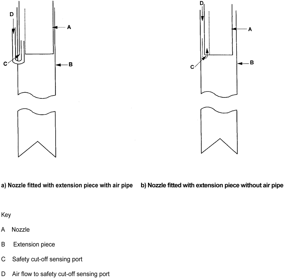
Figure B.1 — Examples of suitable designs for extension pieces
13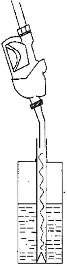
Figure B.2 — Assembly for sampling with a loose fitting nozzle extension
14 15